34
Chapter 2
Information
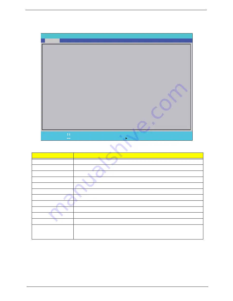
The Information screen displays a summary of your computer hardware information.
NOTE:
The system information is subject to different models.
Parameter
Description
CPU Type
This field shows the CPU type and speed of the system.
CPU Speed
This field shows the speed of the CPU.
IDE0 Model Name
This field shows the model name of HDD installed on primary IDE master.
IDE0 Serial Number
This field displays the serial number of HDD installed on primary IDE master.
ATAPI Model Name
This field displays the model name of the installed ODD drive.
System BIOS Version
Displays system BIOS version.
VGA BIOS Version
This field displays the VGA firmware version of the system.
Serial Number
This field displays the serial number of this unit.
Asset Tag Number
This field displays the asset tag number of the system.
Product Name
This field shows product name of the system.
Manufacturer Name
This field displays the manufacturer of this system.
UUID Number
Universally Unique Identifier (UUID) is an identifier standard used in software
construction, standardized by the Open Software Foundation (OSF) as part of
the Distributed Computing Environment (DCE).
F 1
E S C
H e l p
E x i t
S e l e c t I t e m
S e l e c t M e n u
C h a n g e Va l u e s
S e l e c t
S u b M e n u
E n t e r
F 9
F 1 0
S e t u p D e f a u l t
S a v e a n d E x i t
A M D T u r i o n ( t m ) I I
N 5 3 0 D u a l - C o r e P r o c e s s o r
2 5 0 0 M H z
W D C W D 6 4 0 0 B E V T - 2 2 A 0 R T 0
W D - W X 5 0 A B 9 K 4 8 1 9
S l i m t y p e D V D A D S 8 A 4 S H
V 1 . 0 0
A T i 0 1 2 . 0 2 0 . 0 0 0 . 0 0 5 . 0 3 6 6 9 6
Z R 8 0 S K 0 3 B 1 9 5 1 1 7 4 3 5 2 5 0 0
F
A c e r
4 B A 3 5 5 8 7 5 3 5 D 4 A 8 B B 0 5 C 8 F 3 9 1 D 0 E 2 E 2 E
S e r i a l N u m b e r :
C P U T y p e :
C P U S p e e d :
I D E 0 M o d e l N a m e :
I D E 0 S e r i a l N u m b e r :
A T A P I M o d e l N a m e :
S y s t e m B I O S V e r s i o n :
V G A B I O S V e r s i o n :
A s s e t T a g N u m b e r :
P r o d u c t N a m e :
M a n u f a c t u r e r N a m e :
U U I D :
F 5 / F 6
Main
Boot
Exit
Security
Information
P h o e n i x S e c u r e C o r e ( t m ) S e t u p U t i l i t y
Содержание ASPIRE 553G
Страница 6: ...VI ...
Страница 10: ...X Table of Contents ...
Страница 42: ...32 Chapter 1 ...
Страница 67: ...Chapter 3 57 4 Lift the base door out and away ...
Страница 72: ...62 Chapter 3 5 Pull the WLAN module out and away ...
Страница 80: ...70 Chapter 3 8 Flip the keyboard over 9 Detach the keyboard FPC a Unlock the FPC b Pull the keyboard away a b ...
Страница 86: ...76 Chapter 3 4 Unlock and disconnect the switch board FFC ...
Страница 88: ...78 Chapter 3 4 Lift the power board away ...
Страница 93: ...Chapter 3 83 14 Lift the LCD module out of the assembly ...
Страница 95: ...Chapter 3 85 4 Lift away the USB board 5 Unlock and remove the USB board FFC from the mainboard ...
Страница 104: ...94 Chapter 3 4 Lift the power cable assembly out of the chassis 5 Lift the power cable connector out of the bracket ...
Страница 107: ...Chapter 3 97 4 Pry open the bottom corners and along the bottom edge 5 Lift the bezel off the module ...
Страница 111: ...Chapter 3 101 7 Disconnect the FPC cable ...
Страница 114: ...104 Chapter 3 8 Remove the cable from the retention guides 9 Pry the antenna off the casing ...
Страница 119: ...Chapter 3 109 7 Lay the cables along the retention guides ...
Страница 125: ...Chapter 3 115 3 Press down on the bezel edge working simultaneously around the edges to the bottom ...
Страница 130: ...120 Chapter 3 2 Using a flat bladed screw driver rotate the CPU locking screw 180 clockwise to secure the CPU in place ...
Страница 134: ...124 Chapter 3 4 Connect and lock the USB card FFC to the mainboard ...
Страница 136: ...126 Chapter 3 4 Connect the Bluetooth module cable to the main board ...
Страница 140: ...130 Chapter 3 10 Press the LVDS connector left and right adhesive tabs down onto the mainboard ...
Страница 146: ...136 Chapter 3 7 Connect and lock the button board FFC ...
Страница 152: ...142 Chapter 3 4 Grasp the tab and slide the HDD firmly into the docking connector ...
Страница 154: ...144 Chapter 3 Replacing the ODD Module 1 Replace the ODD bezel 2 Replace the ODD bracket ...
Страница 158: ...148 Chapter 3 ...
Страница 176: ...166 Chapter 5 Mainboard Bottom View VGA HDMI LAN USB MIC Headphone SPDIF Batter DC in ODD HDD FAN WLAN ...
Страница 178: ...168 Chapter 5 ...
Страница 228: ...218 Appendix A ...
Страница 234: ...224 Appendix B ...
Страница 236: ...226 ...
Страница 239: ...229 Index ...