


150
Chapter 4
Power On Issue
If the system doesn’t power on, perform the following actions one at a time to correct the problem. Do not
replace non-defective FRUs:
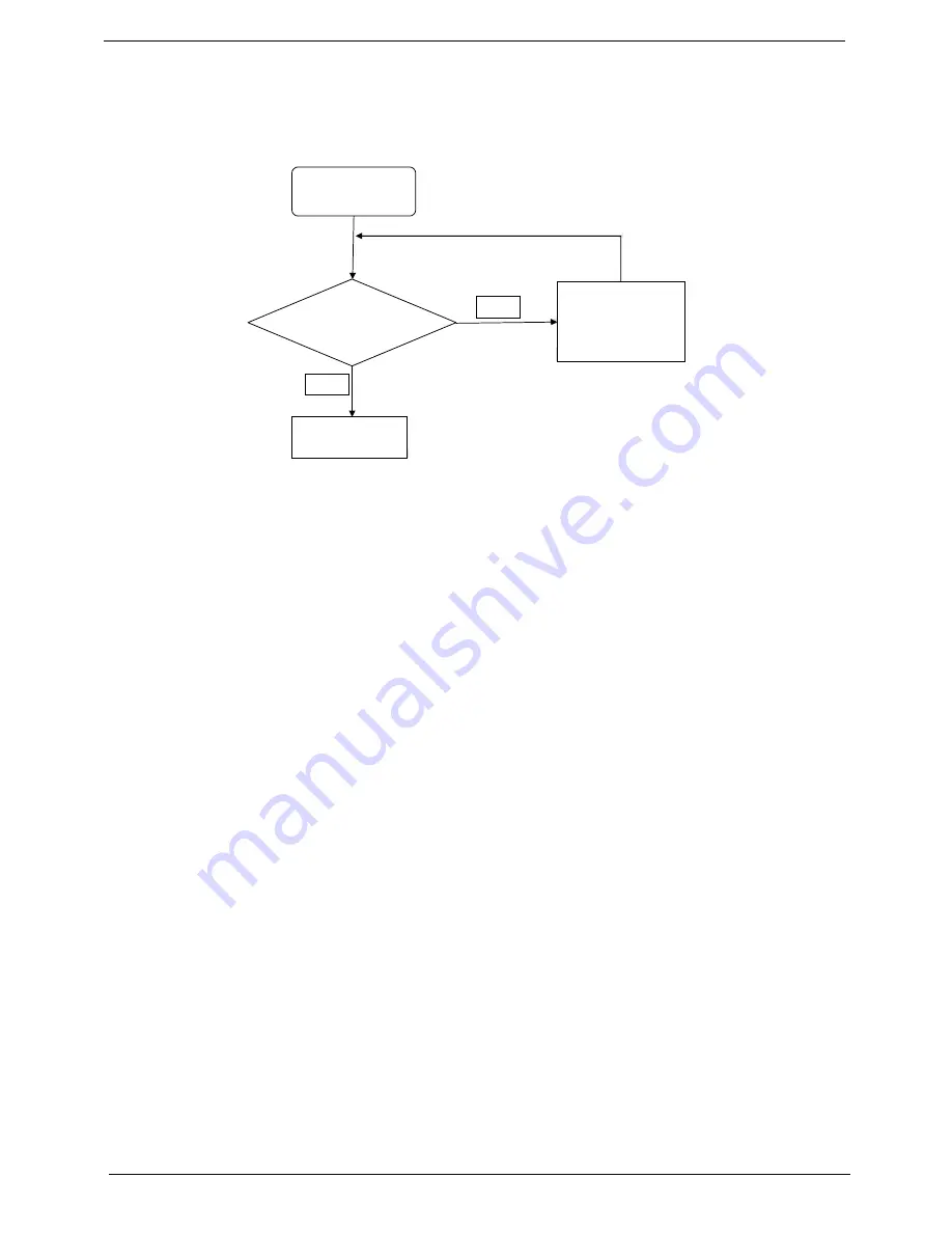
Computer Shuts down Intermittently
If the system powers off at intervals, perform the following actions one at a time to correct the problem.
1.
Check the power cable is properly connected to the computer and the electrical outlet.
2.
Remove any extension cables between the computer and the outlet.
3.
Remove any surge protectors between the computer and the electrical outlet. Plug the computer directly
into a known good electrical outlet.
4.
Remove all external and non-essential hardware connected to the computer that are not necessary to
boot the computer to the failure point.
5.
Remove any recently installed software.
6.
If the Issue is still not resolved, see “Online Support Information” on page 225.
Check
AC/Battery
Swap AC/Battery
try
NG
OK
Swap M/B
Start
Содержание ASPIRE 553G
Страница 6: ...VI ...
Страница 10: ...X Table of Contents ...
Страница 42: ...32 Chapter 1 ...
Страница 67: ...Chapter 3 57 4 Lift the base door out and away ...
Страница 72: ...62 Chapter 3 5 Pull the WLAN module out and away ...
Страница 80: ...70 Chapter 3 8 Flip the keyboard over 9 Detach the keyboard FPC a Unlock the FPC b Pull the keyboard away a b ...
Страница 86: ...76 Chapter 3 4 Unlock and disconnect the switch board FFC ...
Страница 88: ...78 Chapter 3 4 Lift the power board away ...
Страница 93: ...Chapter 3 83 14 Lift the LCD module out of the assembly ...
Страница 95: ...Chapter 3 85 4 Lift away the USB board 5 Unlock and remove the USB board FFC from the mainboard ...
Страница 104: ...94 Chapter 3 4 Lift the power cable assembly out of the chassis 5 Lift the power cable connector out of the bracket ...
Страница 107: ...Chapter 3 97 4 Pry open the bottom corners and along the bottom edge 5 Lift the bezel off the module ...
Страница 111: ...Chapter 3 101 7 Disconnect the FPC cable ...
Страница 114: ...104 Chapter 3 8 Remove the cable from the retention guides 9 Pry the antenna off the casing ...
Страница 119: ...Chapter 3 109 7 Lay the cables along the retention guides ...
Страница 125: ...Chapter 3 115 3 Press down on the bezel edge working simultaneously around the edges to the bottom ...
Страница 130: ...120 Chapter 3 2 Using a flat bladed screw driver rotate the CPU locking screw 180 clockwise to secure the CPU in place ...
Страница 134: ...124 Chapter 3 4 Connect and lock the USB card FFC to the mainboard ...
Страница 136: ...126 Chapter 3 4 Connect the Bluetooth module cable to the main board ...
Страница 140: ...130 Chapter 3 10 Press the LVDS connector left and right adhesive tabs down onto the mainboard ...
Страница 146: ...136 Chapter 3 7 Connect and lock the button board FFC ...
Страница 152: ...142 Chapter 3 4 Grasp the tab and slide the HDD firmly into the docking connector ...
Страница 154: ...144 Chapter 3 Replacing the ODD Module 1 Replace the ODD bezel 2 Replace the ODD bracket ...
Страница 158: ...148 Chapter 3 ...
Страница 176: ...166 Chapter 5 Mainboard Bottom View VGA HDMI LAN USB MIC Headphone SPDIF Batter DC in ODD HDD FAN WLAN ...
Страница 178: ...168 Chapter 5 ...
Страница 228: ...218 Appendix A ...
Страница 234: ...224 Appendix B ...
Страница 236: ...226 ...
Страница 239: ...229 Index ...


