


Chapter 4
151
No Display Issue
If the
Display
doesn’t work, perform the following actions one at a time to correct the problem. Do not replace
non-defective FRUs:
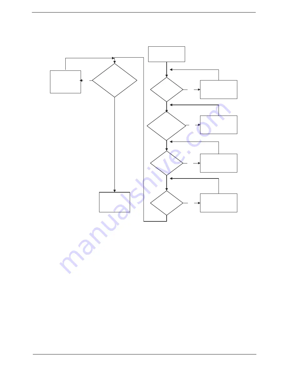
No POST or Video
If the POST or video doesn’t display, perform the following actions one at a time to correct the problem.
1.
Make sure that the internal display is selected. On this notebook model, switching between the internal
display and the external display is done by pressing
Fn+F5
. Reference Product pages for specific model
procedures.
2.
Make sure the computer has power by checking at least one of the following occurs:
•
Fans start up
•
Status LEDs light up
If there is no power, see “Power On Issue” on page 150.
3.
Drain any stored power by removing the power cable and battery and holding down the power button for
10 seconds. Reconnect the power and reboot the computer.
4.
Connect an external monitor to the computer and switch between the internal display and the external
display is by pressing
Fn+F5
(on this model).
If the POST or video appears on the external display, see “LCD Failure” on page 153.
5.
Disconnect power and all external devices including port replicators or docking stations. Remove any
memory cards and CD/DVD discs. Restart the computer.
START
Power On ?
No
Go to No Power
troubleshooting
step
Replace external
DDRAM module
Remove and
replace thermal
module
Replace the
main board
Reconnect
SDRAM Module
LCD Module OK?
Replace LCD
Panel and
Cable
Ext. DDRAM module
connected properly?
Ext. DDRAM
module functional?
CPU Thermal
Module properly
connected?
No
No
No
No
Содержание ASPIRE 553G
Страница 6: ...VI ...
Страница 10: ...X Table of Contents ...
Страница 42: ...32 Chapter 1 ...
Страница 67: ...Chapter 3 57 4 Lift the base door out and away ...
Страница 72: ...62 Chapter 3 5 Pull the WLAN module out and away ...
Страница 80: ...70 Chapter 3 8 Flip the keyboard over 9 Detach the keyboard FPC a Unlock the FPC b Pull the keyboard away a b ...
Страница 86: ...76 Chapter 3 4 Unlock and disconnect the switch board FFC ...
Страница 88: ...78 Chapter 3 4 Lift the power board away ...
Страница 93: ...Chapter 3 83 14 Lift the LCD module out of the assembly ...
Страница 95: ...Chapter 3 85 4 Lift away the USB board 5 Unlock and remove the USB board FFC from the mainboard ...
Страница 104: ...94 Chapter 3 4 Lift the power cable assembly out of the chassis 5 Lift the power cable connector out of the bracket ...
Страница 107: ...Chapter 3 97 4 Pry open the bottom corners and along the bottom edge 5 Lift the bezel off the module ...
Страница 111: ...Chapter 3 101 7 Disconnect the FPC cable ...
Страница 114: ...104 Chapter 3 8 Remove the cable from the retention guides 9 Pry the antenna off the casing ...
Страница 119: ...Chapter 3 109 7 Lay the cables along the retention guides ...
Страница 125: ...Chapter 3 115 3 Press down on the bezel edge working simultaneously around the edges to the bottom ...
Страница 130: ...120 Chapter 3 2 Using a flat bladed screw driver rotate the CPU locking screw 180 clockwise to secure the CPU in place ...
Страница 134: ...124 Chapter 3 4 Connect and lock the USB card FFC to the mainboard ...
Страница 136: ...126 Chapter 3 4 Connect the Bluetooth module cable to the main board ...
Страница 140: ...130 Chapter 3 10 Press the LVDS connector left and right adhesive tabs down onto the mainboard ...
Страница 146: ...136 Chapter 3 7 Connect and lock the button board FFC ...
Страница 152: ...142 Chapter 3 4 Grasp the tab and slide the HDD firmly into the docking connector ...
Страница 154: ...144 Chapter 3 Replacing the ODD Module 1 Replace the ODD bezel 2 Replace the ODD bracket ...
Страница 158: ...148 Chapter 3 ...
Страница 176: ...166 Chapter 5 Mainboard Bottom View VGA HDMI LAN USB MIC Headphone SPDIF Batter DC in ODD HDD FAN WLAN ...
Страница 178: ...168 Chapter 5 ...
Страница 228: ...218 Appendix A ...
Страница 234: ...224 Appendix B ...
Страница 236: ...226 ...
Страница 239: ...229 Index ...


