Chapter 3
95
LCD Module Disassembly Process
IMPORTANT:
Cable paths and positioning may not represent the actual model. During the removal and
replacement of components, ensure all available cable channels and clips are used and that the cables are
replaced in the same position.
NOTE:
The product previews seen in the disassembly procedures may not represent the final product color or
configuration.
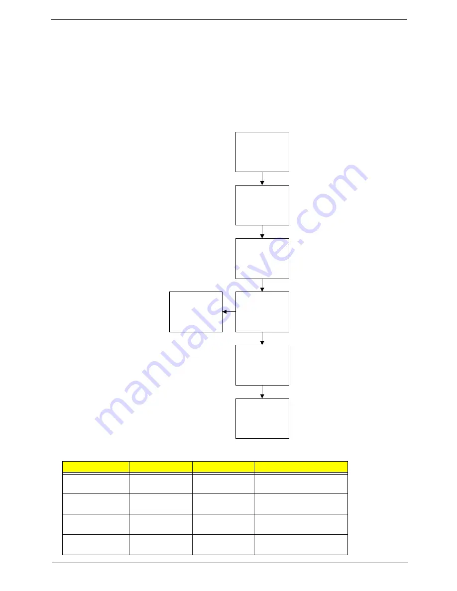
LCD Module Disassembly Flowchart
Screw List
Step
Screw
Quantity
Part No.
LCD Bezel
Disassembly
M2.5*4
2
86.PTN07.004
LCD Panel
Disassembly
M2.5*3
4
86.A08V7.005
Left Hinge
Disassembly
M2.5*3
2
86.PTN07.003
Right Hinge
Disassembly
M2.5*3
2
86.PTN07.003
Remove
Camera Module
Remove
LCD FPC Cable
Remove LCD
Panel from Main
Unit before
proceeding
Remove
LCD Panel
Remove
Antennas
Remove
LCD Bezel
Remove
Microphone
Содержание ASPIRE 553G
Страница 6: ...VI ...
Страница 10: ...X Table of Contents ...
Страница 42: ...32 Chapter 1 ...
Страница 67: ...Chapter 3 57 4 Lift the base door out and away ...
Страница 72: ...62 Chapter 3 5 Pull the WLAN module out and away ...
Страница 80: ...70 Chapter 3 8 Flip the keyboard over 9 Detach the keyboard FPC a Unlock the FPC b Pull the keyboard away a b ...
Страница 86: ...76 Chapter 3 4 Unlock and disconnect the switch board FFC ...
Страница 88: ...78 Chapter 3 4 Lift the power board away ...
Страница 93: ...Chapter 3 83 14 Lift the LCD module out of the assembly ...
Страница 95: ...Chapter 3 85 4 Lift away the USB board 5 Unlock and remove the USB board FFC from the mainboard ...
Страница 104: ...94 Chapter 3 4 Lift the power cable assembly out of the chassis 5 Lift the power cable connector out of the bracket ...
Страница 107: ...Chapter 3 97 4 Pry open the bottom corners and along the bottom edge 5 Lift the bezel off the module ...
Страница 111: ...Chapter 3 101 7 Disconnect the FPC cable ...
Страница 114: ...104 Chapter 3 8 Remove the cable from the retention guides 9 Pry the antenna off the casing ...
Страница 119: ...Chapter 3 109 7 Lay the cables along the retention guides ...
Страница 125: ...Chapter 3 115 3 Press down on the bezel edge working simultaneously around the edges to the bottom ...
Страница 130: ...120 Chapter 3 2 Using a flat bladed screw driver rotate the CPU locking screw 180 clockwise to secure the CPU in place ...
Страница 134: ...124 Chapter 3 4 Connect and lock the USB card FFC to the mainboard ...
Страница 136: ...126 Chapter 3 4 Connect the Bluetooth module cable to the main board ...
Страница 140: ...130 Chapter 3 10 Press the LVDS connector left and right adhesive tabs down onto the mainboard ...
Страница 146: ...136 Chapter 3 7 Connect and lock the button board FFC ...
Страница 152: ...142 Chapter 3 4 Grasp the tab and slide the HDD firmly into the docking connector ...
Страница 154: ...144 Chapter 3 Replacing the ODD Module 1 Replace the ODD bezel 2 Replace the ODD bracket ...
Страница 158: ...148 Chapter 3 ...
Страница 176: ...166 Chapter 5 Mainboard Bottom View VGA HDMI LAN USB MIC Headphone SPDIF Batter DC in ODD HDD FAN WLAN ...
Страница 178: ...168 Chapter 5 ...
Страница 228: ...218 Appendix A ...
Страница 234: ...224 Appendix B ...
Страница 236: ...226 ...
Страница 239: ...229 Index ...