


10
Chapter 1
Indicators
The computer has several easy-to-read status indicators:
The front panel indicators are visible even when the computer cover is closed.
NOTE:
1.
Charging:
The battery light shows amber when the battery is charging. 2.
Fully charged:
The light
shows green when in AC mode.
Easy-Launch Buttons
Located beside the keyboard are application buttons. These buttons are called easy-launch buttons. They are:
WLAN, Internet, email, Bluetooth, Arcade and Acer Empowering Technology.
The mail and Web browser buttons are pre-set to email and Internet programs, but can be reset by users. To
set the Web browser, mail and programmable buttons, run the Acer Launch Manager.
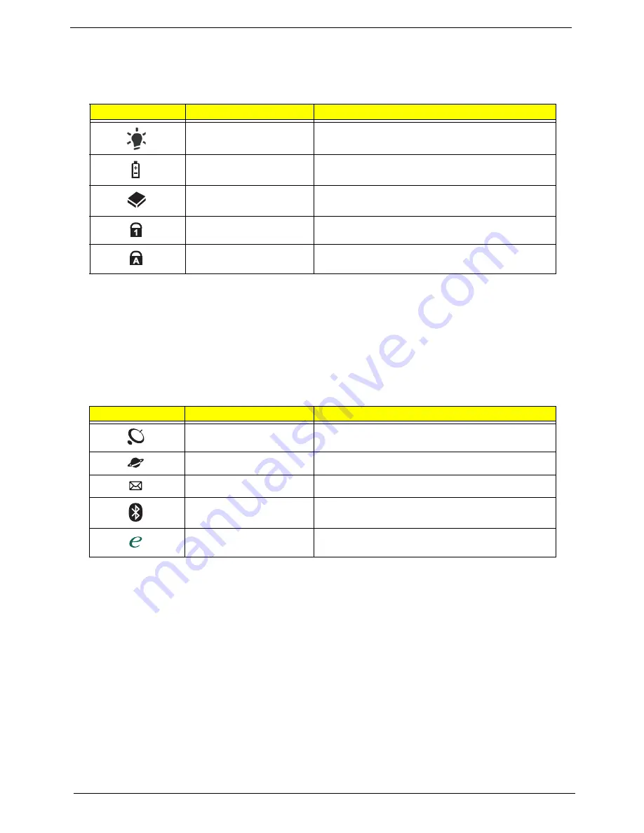
Icon
Function
Description
Power
Indicates the computer's power status.
Battery
Indicates the computer's battery status.
HDD
Indicates when the hard disk drive is active.
Num Lock
Lights up when Num Lock is activated.
Caps Lock
Lights up when Caps Lock is activated.
Icon
Function
Description
Wireless communication
switch
Enables/disables the wireless function.
Web browser
Internet browser (user-Programmable)
Email application (user-Programmable)
Bluetooth communication
switch
Enables/disables the Bluetooth function.
Empowering Technology
Launch Acer Empowering Technology.
(user-programmable)
Содержание Aspire 4935 Series
Страница 6: ...VI ...
Страница 10: ...X Table of Contents ...
Страница 60: ...50 Chapter 2 ...
Страница 68: ...58 Chapter 3 7 Carefully open the HDD Cover ...
Страница 95: ...Chapter 3 85 5 Remove the TouchPad Bracket from the Upper Base ...
Страница 100: ...90 Chapter 3 5 Lift the USB Board clear of the casing ...
Страница 104: ...94 Chapter 3 7 Lift the mainboard right side first to remove from the base ...
Страница 112: ...102 Chapter 3 4 Lift the bezel away from the panel ...
Страница 115: ...Chapter 3 105 4 Lift the LCD Panel out of the casing as shown ...
Страница 122: ...112 Chapter 3 13 Ensure that the securing pin is properly located ...
Страница 130: ...120 Chapter 3 7 Insert the cable through the casing to the top side as shown ...
Страница 143: ...Chapter 3 133 13 Replace the two securing screws ...
Страница 148: ...138 Chapter 3 4 Turn the computer over and replace the six securing screws as shown ...
Страница 154: ...144 Chapter 3 ...
Страница 193: ...Chapter 6 183 ...
Страница 232: ...Appendix A 222 ...
Страница 240: ...230 Appendix C ...


