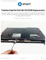
Chapter 3
115
Replacing the Camera Module
1.
Reconnect the LCD cable to the Camera Module.
2.
Place the Camera Module in the casing as shown.
3.
Ensure that the locating pins are correctly seated.
4.
Insert the Camera Bracket left side first to engage
the securing clip.
5.
Lower the bracket into place as shown
6.
Replace the single securing screw.
Содержание Aspire 4935 Series
Страница 6: ...VI ...
Страница 10: ...X Table of Contents ...
Страница 60: ...50 Chapter 2 ...
Страница 68: ...58 Chapter 3 7 Carefully open the HDD Cover ...
Страница 95: ...Chapter 3 85 5 Remove the TouchPad Bracket from the Upper Base ...
Страница 100: ...90 Chapter 3 5 Lift the USB Board clear of the casing ...
Страница 104: ...94 Chapter 3 7 Lift the mainboard right side first to remove from the base ...
Страница 112: ...102 Chapter 3 4 Lift the bezel away from the panel ...
Страница 115: ...Chapter 3 105 4 Lift the LCD Panel out of the casing as shown ...
Страница 122: ...112 Chapter 3 13 Ensure that the securing pin is properly located ...
Страница 130: ...120 Chapter 3 7 Insert the cable through the casing to the top side as shown ...
Страница 143: ...Chapter 3 133 13 Replace the two securing screws ...
Страница 148: ...138 Chapter 3 4 Turn the computer over and replace the six securing screws as shown ...
Страница 154: ...144 Chapter 3 ...
Страница 193: ...Chapter 6 183 ...
Страница 232: ...Appendix A 222 ...
Страница 240: ...230 Appendix C ...