62
Chapter 4
System Check Procedures
External Diskette Drive Check
Do the following steps to isolate the problem to a controller, driver, or diskette. A write-enabled, diagnostic
diskette is required.
NOTE:
Make sure that the diskette does not have more than one label attached to it. Multiple labels can cause
damage to the drive or cause the drive to fail.
Do the following to select the test device.
1.
The FDD heads can become dirty over time, affecting their performance. Use an FDD cleaning kit to clean
the heads. If the FDD still does not function properly after cleaning, go to next step.
2.
Boot from diagnostic program.
3.
If an error occurs with the internal diskette drive, reconnect the diskette connector on the main board.
If the error still remains:
1.
Reconnect the external diskette drive module.
2.
Replace the external diskette drive module.
3.
Replace the main board.
External CD-ROM/DVD-ROM Drive Check
Do the following to isolate the problem to a controller, drive, or CD-ROM/DVD-ROM. Make sure that the CD-
ROM does not have any label attached to it. The label can cause damage to the drive or can cause the drive to
fail.
Do the following to select the test device:
1.
Insert an audio CD into the CD/DVD drive. If the CD/DVD drive can read the data from the audio CD. The
drive does not have problem, then go to next step. If the CD/DVD LED on the front panel does not emit
light as it read the data from the audio CD, then go to next step. However, if the CD/DVD drive can not
read data from the audio CD, you may need to clean the CD/DVD drive with a CD/DVD drive cleaning
disk.
2.
Make sure that the appropriate driver has been installed on the computer for the CD/DVD drive.
3.
Boot from the diagnostics diskette and start the diagnostics program
4.
See if CD-ROM Test is passed when the program runs to CD-ROM/DVD-ROM Test.
5.
Follow the instructions in the message window.
If an error occurs, reconnect the connector on the main board. If the error still remains:
1.
Reconnect the CD-ROM/DVD-ROM module.
2.
Replace the CD-ROM/DVD-ROM module.
3.
Replace the main board.
Содержание Aspire 2000
Страница 11: ...4 Chapter 1 Board Layout Top View Rear View ...
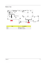
Страница 84: ...Chapter 5 77 Bottom View Item Description JP28 Mini PCI Connector JP30 SO DIMM0 Connector ...
Страница 86: ...78 Chapter 6 Exploded Diagram ...
Страница 87: ...Chapter 6 79 ...
Страница 101: ...93 Appendix C ...


