Chapter 1
3
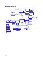
System Block Diagram
Mini-PCI slot
Power OK CKT.
Mini PCI
socket
ATA-100
Memory BUS(DDR)
RTC CKT.
FIR
Touch Pad
MDC & BT Conn
Clock Generator
uFCBGA-479/uFCPGA-478 CPU
Audio CKT
Primary IDE
IEEE 1394
TSB43AB21A
BGA-421
ENE KB910Q
ICS 950810
Super I/O
400MHz
AC-LINK
Int.KBD
LPC BUS
ALC202
BIOS
CRT & TV-OUT Conn.
RTL 8101L
H_D#(0..63)
DDR-SO-DIMM X2
USB2.0
H_A#(3..31)
Fan Control
AGP BUS
Hub-Link
SMsC LPC47N227
EC I/O Buffer
DC/DC Interface CKT.
Power Circuit DC/DC
uFCBGA-593
Secondary IDE
LAN
PSB
Power On/Off CKT.
2.5V DDR- 200/266/333
CardBus Controller
Slot 0
CDROM
Connector
ATA-100
PARALLEL
RJ45/11 CONN
BANK 0, 1, 2, 3
Mobile Banias/Dothan
Intel ICH4-M
AMP & Audio Jack
HDD
Connector
USB conn
Thermal Sensor
ADM1032AR
VGA Board Connector
Intel ODEM RevB
MCH-M
ENE CB1410
Содержание Aspire 2000
Страница 11: ...4 Chapter 1 Board Layout Top View Rear View ...
Страница 84: ...Chapter 5 77 Bottom View Item Description JP28 Mini PCI Connector JP30 SO DIMM0 Connector ...
Страница 86: ...78 Chapter 6 Exploded Diagram ...
Страница 87: ...Chapter 6 79 ...
Страница 101: ...93 Appendix C ...


