30
Chapter 1
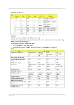
NOTE:
*1. The inverter can work in 7.5V input voltage (continuous), but 7.5V electronic characteristic will
not be care.
*2. Limited lamp maximum current by DAC_BRIC signal:
When DAC_BRIG voltage is 0V and INV_PWM enables (100%), lamp has max. current.
When DAC_BRIG voltage is 3.3V and INV_PWM enables (100%), lamp has min. current.
When add 1V DAC, the 100% Lamp current will decrease 0.5mA.
DAC_BRIG signal comes from system chipset with internal resistance of 3K
*3. Inverter operating frequency should be within specification (45~65kHz) at max. and min.
brightness load.
*4. INV_PWM enable implies INV_PWM signal is High level (On duty cycle is 100%). It is a square
wave of 150Hz to adjust backlight brightness that is a function of PWM duty cycle. Backlight
brightness is maximum value under INV_PWM at 100% and brightness is minimum under
INV_PWM at 30%.
*5.The system interface signals belong to 3.3V.
*6. Please make sure open lamp output voltage should be within starting voltage specification.
*7. Inverter should pass human body safety test.
*8. Inverter should be no smoking by any component open/short test.
*9. Transformer voltage stress should not be over 85% under any condition.
(turn on overshoot transient and line transient.)
*10. Audio noise should be less than 36dB at 10cm distance.
15
Turn off
voltage
(Low
side)
Voff
--
--
150Vp
-p
V
PWM=30%
16
Voltage
Rise time
(Low
side)
Trise
--
--
300us
us
PWM=30%
17
Voltage
fall time
(Low
side)
Tfall
--
--
300us
us
PWM=30%
No
.
Paramete
r
Symbol
Min.
Typ.
Max.
Unit
Comment
Ω
Содержание Aspire 2000
Страница 11: ...4 Chapter 1 Board Layout Top View Rear View ...
Страница 84: ...Chapter 5 77 Bottom View Item Description JP28 Mini PCI Connector JP30 SO DIMM0 Connector ...
Страница 86: ...78 Chapter 6 Exploded Diagram ...
Страница 87: ...Chapter 6 79 ...
Страница 101: ...93 Appendix C ...

