Chapter 3
55
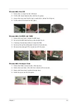
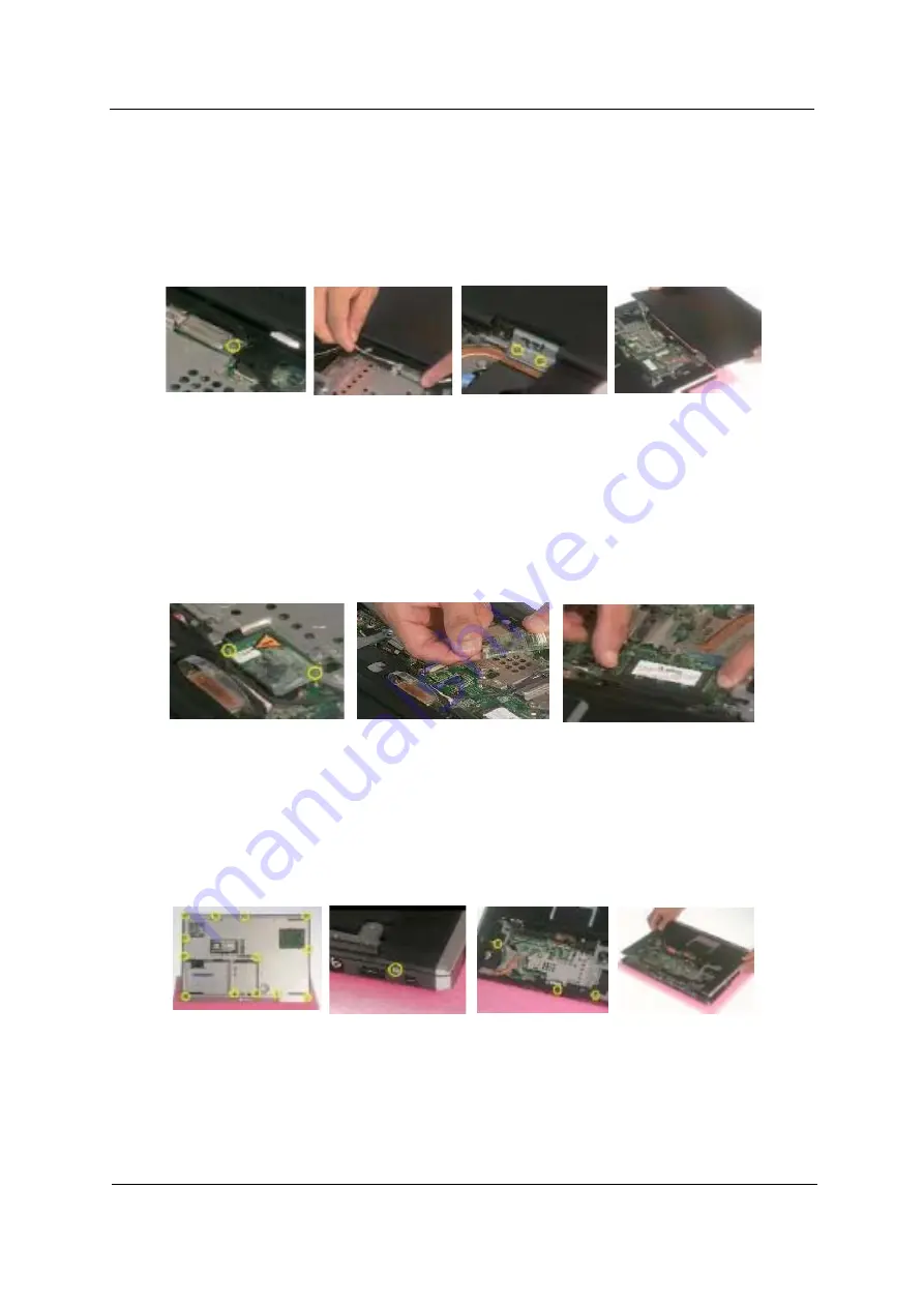
Disassemble the LCD
1.
Remove the one screw from the LVDS board.
2.
Pull the LCD coaxial board and the cable from the system.
3.
Remove the two screws from the hinge on each side to release the LCD panel.
4.
Pull the entire LCD module from the system.
Disassemble the MDC and RAM
1.
Remove the two screws to release the MDC board.
2.
Disconnect the MDC cable before you take the MDC board.
3.
Press down the both sides latches to release the RAM.
4.
Disconnect the right and left speaker cables from the mainboard.
5.
Disconnect the touchpad FPC connector and CPU fan cable.
Disassemble the Upper Case
1.
Remove the thirteen screws located on the base case.
2.
Remove the two screws on the other side to located on the rear panel.
3.
Remove the three screws to release the upper case.
4.
Detach the upper case from the system.
Содержание Aspire 2000
Страница 11: ...4 Chapter 1 Board Layout Top View Rear View ...
Страница 84: ...Chapter 5 77 Bottom View Item Description JP28 Mini PCI Connector JP30 SO DIMM0 Connector ...
Страница 86: ...78 Chapter 6 Exploded Diagram ...
Страница 87: ...Chapter 6 79 ...
Страница 101: ...93 Appendix C ...


