OPERATION
Power-on >
To turn on the projector, press
POWER
on the keypad. Hold
POWER
down for about one second. lf using an IR remote keypad, point the keypad at the
projection screen or the front of the projector. During power-on, the projector proceeds
through a series of internal diagnostic tests, which last approximately 9 seconds. Once
complete, an input image should be displayed on the projection screen. If no image is
displayed, press
SOURCE
to display the source message. The source message displays
the currently selected input. Check that the correct source is indicated on the display.
If there is no display when
*
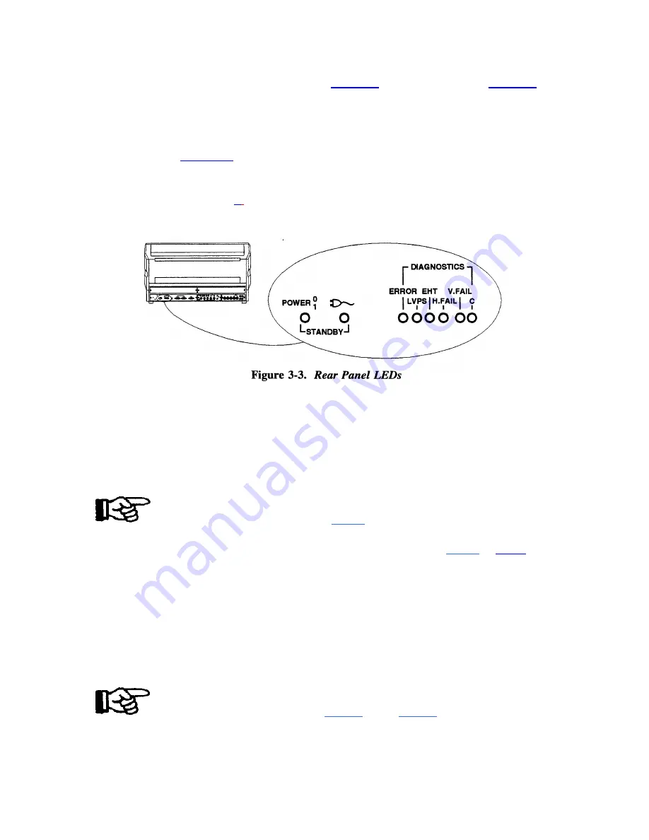
is pressed, check the LEDs (Light Emitting Diodes) on the
projector back panel. Only the green
POWER
LED should be lit. If any of the red
diagnostics LEDs are lit, call
your dealer for assistance.
Notes: 1) Allow the projector to warm up for 45 minutes before use. Critical
adjustments
should be performed after the warm-up period. 2) Turning the
projector off via a remote
or built-in keypad places the projector in a ''wait to
operate'' mode. To remove power
from
the projector, unplug the power cord.
Standby Mode >
Standby
Mode allows you to blank the display and mute the audio output while
keeping the projector in a warmed-up and ready state.
To enter standby mode, hold down
STBY
for about one second while at
presentation level. The display blanks and audio is muted
.
Both the green
POWER
LED
and the yellow plug LED are lit. To leave standby mode, hold down
STBY
or
EXIT
for
one second. The display and audio are then restored and the plug
LED is turned off.
Tip: During presentations, the standby feature is useful when you want to direct audience
attention
away
from the projection screen.
Note: To prolong CRT life, it is recommended that the standby feature be used when the
display is not required.
Audio Functions >
Mute
The Mute function is used to silence audio output.
To silence the audio output, press
MUTE
.
Press
MUTE
again to restore audio.
3-8
Содержание Model 9
Страница 1: ......
Страница 44: ...INSTALLATION SETUP Figure 2 29 ACON Installation Examples 2 38...
Страница 104: ...Physical Dimensions 5 5...
Страница 105: ...5 6...
Страница 113: ...A p p e n d i x B B 1...
Страница 114: ...B 2...
Страница 115: ...C 1...
Страница 116: ...C 2...
Страница 117: ...D 1...
Страница 118: ...D 2...
Страница 119: ...E 1...
Страница 120: ...F 1...
Страница 121: ...F 2...
Страница 122: ...F 3...
Страница 123: ...F 4...
Страница 124: ...F 5...
Страница 125: ...F 6...
Страница 126: ...F 7...
Страница 127: ...F 8...
Страница 128: ...F 9...
Страница 129: ...F 10...
Страница 130: ...G 1...
Страница 131: ...Index 1...
Страница 132: ...Index 2...


