background image

INSTALLATION & SETUP


Step 2 

Case Removal 

Locate the four screws around the base perimeter of the back portion of the fiberglass 
case, and the four screws on the base perimeter of the front portion of the fiberglass case. 
Unscrew these screws, and then gently slide the front cone off, pulling away from the 
center, straight out.  You will now see two new screws located on top of the frame. These 
screws are the last screws holding the rear fiberglass portion to the projector.  Remove 
these screws and gently pull the case off the backside, straight out.  

Case Placement 

The placement of the case back on the projector is just as simple as its removal.  Just be 
sure to put the rear section of the case on the projector before the front portion. 
 
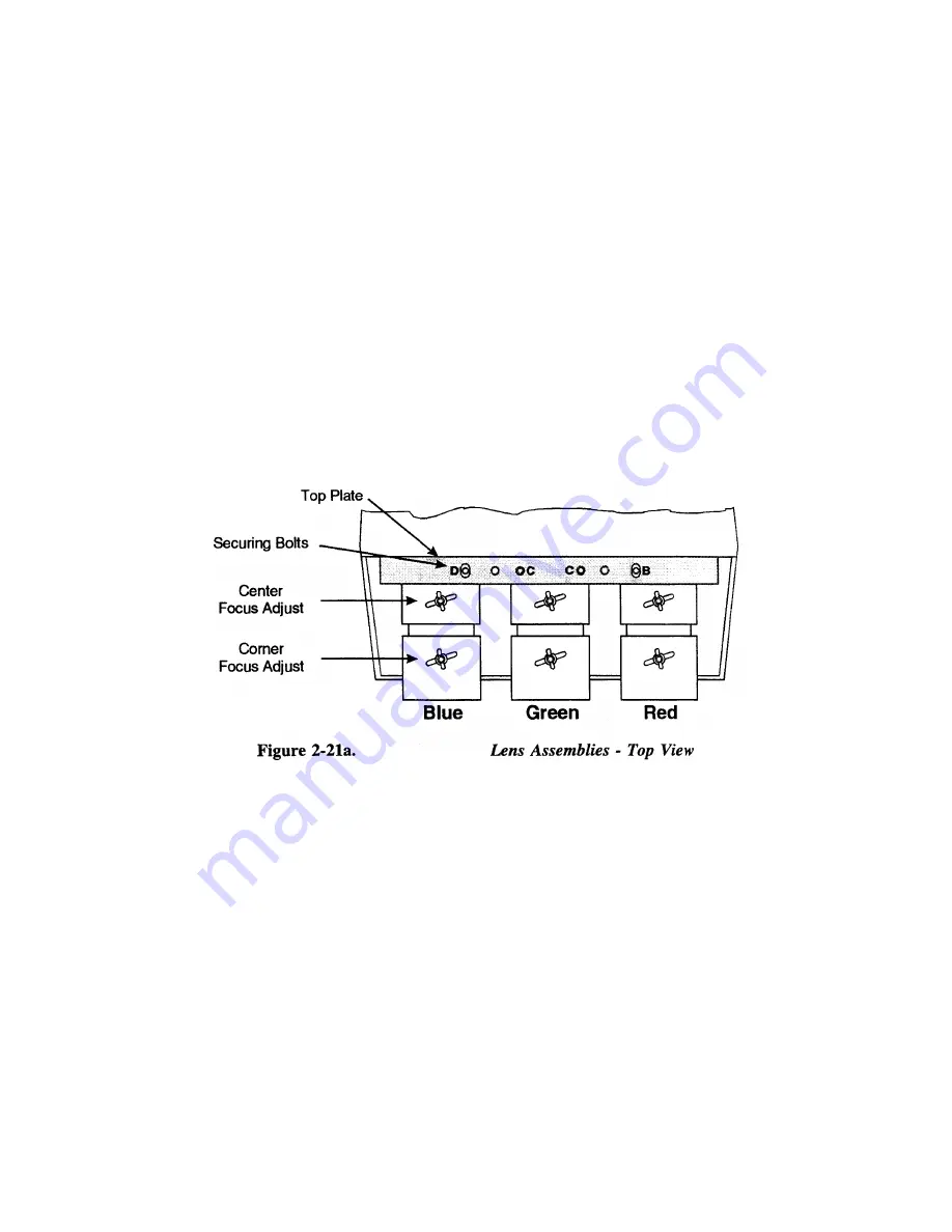
Examine the lenses and hardware as shown in Figure 2-21a (or, for the model 8, see 
Figure 2-21b).


Each lens consists of a rear section and a front section. The rear section 

sets the optical focus at the center of the image and is secured to the lens body by a wing 
nut at the top rear of the lens assembly. The front section sets the focus at the corners and 
is secured to the rear section by a wing nut at the top front of the lens assembly. 


2-17 

Содержание Model 9

Страница 1: ......

Страница 2: ...Image Shifter Setup 2 32 2 12 ACON Setup 2 37 3 Operation 3 1 Overview 3 1 3 2 Projector Basics 3 1 3 3 Source Selection 3 10 3 4 Setup Memories 3 13 3 5 Display Adjustments 3 15 3 6 Convergence Regi...

Страница 3: ...nterference and 2 This device must accept any interference received including interference that may cause undesired operation This Class A digital apparatus meets all the requirements of the Canadian...

Страница 4: ...America is for the 120 Volt position SCANNING CONFIGURATIONS FLOOR CEILING FRONT REAR WARNING THE SCANNING CONFIGURATION PROCEDURE MUST BE PERFORMED ONLY BY A QUALIFIED SERVICE TECHNICIAN Typographica...

Страница 5: ...ard on Model 9 Optional ACON 11 automatic convergence feature Functional Description The projector accepts data graphics and video input signals from a variety of sources for projection onto flat curv...

Страница 6: ...if you need assistance for upgrading your projector contact your dealer or Accurate Imaging 1 2 Purchaser s Record and Servicing Whether the projector is under warranty or the warranty has expired Ac...

Страница 7: ...Optical Alignment Step 2 Connect the Power Cord Plug the AC line cord into the line input unit on the lower front panel of the projector Plug the three prong end of the line cord in a grounded AC out...

Страница 8: ...udience May be accidentally moved necessitating realignment Front Screen Ceiling Mount Installation ADVANTAGES Does not take up audience space The projector is less noticeable The projector cannot be...

Страница 9: ...screen types are illustrated in Figures 2 1 and 2 2 Flat screens offer a gain of about 1 with a viewing angle just less than 1800 Incident light reflects equally in all directions so the audience can...

Страница 10: ...are interrelated See Appendices F and G As screen size increases the distance between the projector and the screen also increases During projection room design make sure that the room can accommodate...

Страница 11: ...you an idea of what makes a good projection environment A1l walls floors and furnishings are dull colored and non reflectively finished Every effort should be made to create the best environment for...

Страница 12: ...em Proper ventilation is important The ambient temperature should be kept constant and below 35 degrees C 95 degrees F Keep the projector away from heating and or air conditioning vents Changes in tem...

Страница 13: ...itioning the projector and screen in a manner which will achieve maximum audience coverage and space efficiency For example placing the screen along the larger wall in a rectangular room will reduce a...

Страница 14: ...then pull straight out from the center of the projector The keypad is mounted to a securing bracket located above the lens assemblies Loosen the two bracket wing nuts then move the keypad away from t...

Страница 15: ...mote move the JP4 jumper from between pins 2 and 3 to between pins 1 and 2 Step 3 For an IR remote keypad place four AA size 1 5V alkaline batteries in the compartment ensuring that the orientation of...

Страница 16: ...r disable press BRITE TINT DETAIL then 3 To return all configuration settings to the jumper settings press BRITE TINT DETAIL then 0 Note The projector will not respond to keypad commands you press BRI...

Страница 17: ...cation with the projector pointing towards the center of the projection screen The angle of projection combined with the tilt angle of the screen should direct the reflected image towards the center o...

Страница 18: ...wards the center of the audience It is recommended that the difference between the projection angle and the screen tilt angle within a common reference be less than 15 degrees See to Figure 2 11 Instr...

Страница 19: ...n Figure 2 14 If a diffused screen is used the projection angle 0 should be less than 15 degrees If an optical screen is used the optical path between the mirror and the screen should be perpendicular...

Страница 20: ...lt in interface is not removable Optional interface modules are available to accommodate other signal types These include a Composite a video Module an HDTV Input Module and a PC Analog Input Module A...

Страница 21: ...he vertical sync input to the VERT input Interconnection cables must be terminated with BNC connectors Figure 2 17 show source connections for the built in interface To control audio levels in an audi...

Страница 22: ...e factory at a fixed screen size and a fixed projector to screen distance See Appendices F and G for the specific details needed for your projector model and lens If the throw distance has changed sin...

Страница 23: ...ws and gently pull the case off the backside straight out Case Placement The placement of the case back on the projector is just as simple as its removal Just be sure to put the rear section of the ca...

Страница 24: ...ball nose screwdriver supplied with the projector Adjust the mounting plate securing bolts using either the ball nose screwdriver or the projector wrench supplied as necessary The securing bolts are...

Страница 25: ...Loosen the rear wing nut on the green lens Rotate the lens using the wing nut until the picture is focused in the center Tighten the rear wing nut Step 4 Loosen the front wing nut on the green lens R...

Страница 26: ...ng nut on the red lens Rotate the front lens barrel until the picture is focused in the corners Tighten the front wing nut Step 14 A blue image is displayed Loosen the rear wing nut on the blue lens R...

Страница 27: ...d D Step 23 A green image is displayed Loosen the rear wing nut on the green lens and slightly defocus the center of the picture Step 24 On the Model 9 locate the two adjustment bolts at the upper rig...

Страница 28: ...right corner of the red lens mounting plate viewed from the front Adjust the two bolts until the top and bottom areas of the picture are equally defocused Use the same technique as that used for the g...

Страница 29: ...p and bottom areas of the picture are equally defocused Use the same technique as that used for the green and red adjustments On the Model 8 adjust the large allen head bolt located at the blue lens m...

Страница 30: ...the projector for a selected external source For a complete setup repeat these steps as required for each source connected to the projector Before starting ensure that the projector is optically and m...

Страница 31: ...EFT or RIGHT to adjust side pincushion until the left and right sides of the picture are straight and not curved Step 7 Press UP or DOWN to adjust vertical bow until the horizontal line at the middle...

Страница 32: ...WN LEFT or RIGHT to adjust the size of the picture Ensure that objects in your picture have the correct shape For example if there is a circle in your picture size should be adjusted until the circle...

Страница 33: ...setup memory is locked Note If the ASR feature explained below is turned on during setup memory selection the selected memory may not be the current setup memory To display the Recall memories stored...

Страница 34: ...e display appearance may improve based on the settings stored in other setup memories If the Input memory is new ASI with Save will have already been performed when the input was selected Step 3 Make...

Страница 35: ...display adjustments are made the display settings are stored in the current setup memory Prepare a Recall memory using the generator as follows Step 1 Select a Recall memory to be the current setup me...

Страница 36: ...m follow these steps Step 1 Select the input using the Source command Press SOURCE 0 then 1 to select projector slot 1 Step 2 Press twice to display the Current Input Parameters status page Check to s...

Страница 37: ...er if ASR is turned on for the input and a Recall memory has been set up for each source device the projector will detect the external source switch and automatically select the appropriate Recall mem...

Страница 38: ...t The projector s display settings will automatically adjust to match the source selected by the switcher 2 11 Image Shiner Setup This section provides setup and usage information about the Image Shif...

Страница 39: ...ne of the following sync types sync on green 3 wire composite 4 wire and separate H V 5 wire To connect a source connect the red green and blue outputs to the RED GREEN and BLUE inputs on the interfac...

Страница 40: ...The slave units are those in the chain that have a cable connected to MULTI IN The unit with only MULTI OUT connected is the master See Figure 2 27 below Note It is recommended that a rough setup be p...

Страница 41: ...ext reduce the left right top and bottom blanking levels as much as possible to maximize the visible display area Adjust the H CENT and V CENT controls to center the image within the display raster To...

Страница 42: ...LOW switch to SLOW The image will now slowly shift its position between the left edge and right edges and top and bottom edges of the raster The left or right shift duration is approximately 125 secon...

Страница 43: ...ocator Assembly analyzing this data then adjusting the vertical and horizontal positions of the red and blue colors until optimum convergence with the green is achieved This process requires that the...

Страница 44: ...INSTALLATION SETUP Figure 2 29 ACON Installation Examples 2 38...

Страница 45: ...ti projector Functions 3 2 Projector Basics Notice that the projector has no knobs or moving parts to make adjustments or change control settings This is because all user adjustments are digitally con...

Страница 46: ...k in place IR Remote Keypad When the keypad is configured for IR remote operation you can control the projector from a distance without a wired connection to the projector The keypad includes a batter...

Страница 47: ...l function keypad As you may notice from the figure some keys provide direct access to specific functions such as POWER to turn the projector on or off and some keys provide indirect function access v...

Страница 48: ...ector is turned on it begins operation at Presentation Level Presentation level is the normal level of operation at which a source image is or may be displayed The projector temporarily leaves present...

Страница 49: ...r bar Selection items may include adjustment functions control settings or other menus To make a selection from the menu either Press the number key corresponding to the item number or Press UP or DOW...

Страница 50: ...to assist you during projector setup Press to display the first test pattern a crosshatch Each subsequent press of changes the test pattern as shown below If a test pattern is the only graphic displa...

Страница 51: ...rough the tutorial Notes 1 During the tutorial RECALL displays the previous page and EXIT returns you to presentation level this includes when slidebars are displayed 2 If the display cannot be focuse...

Страница 52: ...itical adjustments should be performed after the warm up period 2 Turning the projector off via a remote or built in keypad places the projector in a wait to operate mode To remove power from the proj...

Страница 53: ...time keypad type scan configuration auto power up setting message display setting switchers numbers connected installed options and mute setting Operating settings are explained in the following entr...

Страница 54: ...rect input selection may be the only method you will use If your system includes many sources all methods will be of interest 2 Internal sources are also selectable for use during setup and testing To...

Страница 55: ...when a switcher is connected to slot 1 of the projector Another example of an invalid input would be to select a switcher which does not physically exist Example 1 Slot 1 on the projector has the out...

Страница 56: ...gits the preceding zero shown in the example above does not have to be entered For more information refer to the Preferences entry in Section 3 7 Up Down Channel Selection This method of source select...

Страница 57: ...h are locked are not affected by adjustments to display settings For an explanation of Input memories and locked memories refer to section 3 4 Setup Memories Recall Memory Number When a Recall memory...

Страница 58: ...ach physical input i e switcher 0 slot 1 When an input is selected the Input memory for that input becomes the current setup memory and its display settings are used unless ASR is on and is triggered...

Страница 59: ...locked and selected then brightness is adjusted the new brightness setting is only temporary If the setup memory is then reselected the original brightness setting will be restored Note When a locked...

Страница 60: ...ng many picture or geometry adjustments press ENTER after each adjustment to return the Cursor back to its previous menu item position Primary Display Adjustments Brightness The Brightness function is...

Страница 61: ...here shows the selection variations Tint The Tint function is used to adjust color hue to obtain true color reproduction of NTSC signals when using the optional Multi standard Decoder To adjust tint...

Страница 62: ...select or adjust the white balance select White Balance from the Picture menu From the White Balance menu select item 1 2 or 3 to use a standard color temperature Select option 4 to use the service a...

Страница 63: ...gnals auto clamp should be on However if one or more of the red green or blue color components is abnormally bright turn auto clamp off An abnormally bright color component can occur if the input sign...

Страница 64: ...and As RGB The current selection is indicated by a check mark Auto detect is the default When Auto detect is the selected option the projector determines whether the input signal requires routing thr...

Страница 65: ...the Decoder Similarly the system allows you to connect S video Y C signals to the Red for Y and Blue for C BNCs where they are routed to the Decoder if the Recall or input memory assigned to the S vid...

Страница 66: ...It is usually easier to adjust display geometry while a test pattern is displayed GEOM 1 Size The Size function is used to adjust the horizontal and vertical size of the display image This adjustment...

Страница 67: ...y menu and press LEFT or RIGHT To adjust top pincushion press UP or DOWN until the top half of the image is as curved or as straight as desired GEOM 5 Bottom The Bottom function adjusts the level Bott...

Страница 68: ...t the left middle and right of the screen have the same horizontal size GEOM 8 S Linearity The S Linearity function corrects for vertical and horizontal non linearities which extend from the center of...

Страница 69: ...be saved in the current setup memory Next press CONV to display the Convergence menu Select one of the convergence options from the menu Note If the projector does not include the ACON automatic Conv...

Страница 70: ...u to select Guided Convergence An internally generated crosshatch is displayed for the alignment Initially a red and green crosshatch is displayed and a rectangular box surrounds the center convergenc...

Страница 71: ...gence The primary difference between Guided Convergence and Interpolated Convergence is noticed during adjustment In Interpolated convergence adjustments are not limited to single zones but will affec...

Страница 72: ...ssage if there is one Note The ACON Auto convergence Menu is available only if the projector includes the optional ACON feature Before using ACON for the first time it is important to understand how A...

Страница 73: ...N S proprietary interpolation software This software provides fast accurate convergence adjustment of poorly converged images During automatic convergence you will notice a small red green or blue squ...

Страница 74: ...sually required only once for each new installation A Learn Screen MUST be performed when one of the following conditions exist The throw distance has changed since the last Learn Screen The ACON Loca...

Страница 75: ...o continue with the Learn Screen operation The remainder of the Learn Screen process is handled automatically by ACON Wait until it is complete at which time the ACON Auto convergence Menu is returned...

Страница 76: ...e originating memory remains unchanged and the destination memory is overwritten with the settings of the originating memory To copy a setup memory press 1 from the Source Setup menu A dialog box is d...

Страница 77: ...eases ASI accuracy improves UTIL 1 3 Current Setup Locked unlocked This utility allows you to lock or unlock the current setup memory Locking a setup memory prevents changes to display settings from b...

Страница 78: ...If an Input memory with matching scan frequencies was found by ASI its settings are used and its identity is displayed If an interpolation was performed the two setup memories selected for the interpo...

Страница 79: ...r s slot 1 input When ASR is on and a source is selected by the switcher the projector automatically adjusts its display settings for the new source by switching to the Recall memory set up for that s...

Страница 80: ...terpolations between setups To select an internal frequency press 6 Select Internal Frequency from the Source Setup menu The resulting menu allows you to choose the scan frequencies of the internal ge...

Страница 81: ...e held may be cleared by pressing NOTE lf a channel is selected and ASR is on for the same input and the incoming frequency does not match the selected setup memories frequency it may cause the follow...

Страница 82: ...ter a check mark press a number key 0 9 To clear a check mark press Note Channels should contain valid inputs For example do not specify switcher 1 if switcher 1 does not exist in the system RECALL ME...

Страница 83: ...the projector To display the Preferences menu press 5 from the Utilities menu Six preference items are displayed with their current settings Select an item to change its setting Defaults shown UTIL 5...

Страница 84: ...u to change its setting 1 Digit Only allows only one digit to be entered after which the projector switches immediately to the selected channel This method can select only channels 1 to 9 2 Digits req...

Страница 85: ...nt setting Four settings are available A or B A B and Off If set to A the projector will only respond if the keypad is set for protocol A operation lf set to B the projector will only respond if the k...

Страница 86: ...0 to 999 If there is only one projector in the installation 000 is the recommended projector number For more information about multi projector control refer to section 3 8 Multi projector Functions Ba...

Страница 87: ...assumed and handled Date To edit the date stored in the real time clock calendar press 2 from the Set Clock menu This puts you in date editing mode A flashing cursor is positioned at the first digit...

Страница 88: ...move the cursor to the field you want to modify for example the Type field Next use ENTER and or the number keys to modify that field Details for field modification are provided on the following pages...

Страница 89: ...ough the available events Press to clear the entire event line Events are described in Table 3 1 below The Interval Field The Interval field shows a date or interval at which the event is to take plac...

Страница 90: ...event is scheduled to begin before the first event is complete otherwise the second event may be ignored For example do not schedule an event to take place one minute after a full ACON auto convergenc...

Страница 91: ...n a multi projector installation it is usually desired to have a single IR keypad control all the projectors in the system This section explains the special control functions available for such instal...

Страница 92: ...ntended to alert the user to the presence of uninsulated dangerous voltage within the projector s enclosure that may be of sufficient magnitude to constitute a risk of electric shock to persons Projec...

Страница 93: ...conditions exist unplug the projector from the power outlet and refer service to qualified service personnel The power cord has been damaged Liquid has been spilled into the projector The projector h...

Страница 94: ...ojector power up Hold down POWER for at least one second to initiate power up 2 If using an IR keypad ensure it is pointed at the screen or the front of the projector lf the keypad is configured for b...

Страница 95: ...initiate the action Like POWER STBY and MUTE must be pressed down for at least one second Symptom The projector does not respond to an IR Remote keypad Cause Remedy 1 The projector s IR keypad listeni...

Страница 96: ...from the Picture Adjust menu PIC Adjust phase so that the entire picture is visible and centered Symptom One side of the display is cut off Cause Remedy 1 A left or right blanking adjustment may be re...

Страница 97: ...p or clean Cause Remedy 1 Display adjustment may be required Adjust the brightness contrast focus and detail settings 2 Is a BNC T connector being used Use a distribution amplifier to boost signal lev...

Страница 98: ...e Remedy 1 Is the active setup memory locked Press SOURCE to display the Source Message If a key is displayed unlock the setup Press UTIL 1 3 2 ASR is set to On for the current input memory and an ASI...

Страница 99: ...performed if The throw distance has changed since the last time Learn Screen was performed The ACON Locator Assembly mounting position has changed since the last time Learn Screen was performed The sc...

Страница 100: ...try circuits separately correct top bottom and sides for flat curved or rear screens up to 25 feet diagonal Keystone circuitry to correct pictures for angles greater than 150 vertically from screen ax...

Страница 101: ...14 kHz to 152 kHz autolock Size automatically regulated over frequency range and adjustable by 15 With left and right blanking control set to 0 Notes 1 Blanking can be Increased with left and right bl...

Страница 102: ...of Inputs 78 Control Features Multi language software user selectable Menu driven interface with on screen help Built in set up tutorials Auto power up after power interruption Six built in test patte...

Страница 103: ...provals FCC Class A DHHS and HWC requirements EN55022 Class B CSA UL EN 60 950 EU Directives 73 23 EEC 89 336 EEC CE marked Further information Proceed to the Accurate website for further technical di...

Страница 104: ...Physical Dimensions 5 5...

Страница 105: ...5 6...

Страница 106: ...y in section 3 7 Utility Features Active Line Time The time inside one horizontal scan line during which video is generated Ambient Light The ability of a screen to reject ambient light in a direction...

Страница 107: ...mage It does not refer to the brightness of a white image The Kelvin K temperature scale is used to measure color temperature Color Temperature Uniformity The accuracy of color temperature at any loca...

Страница 108: ...d off a matte white wall Curved screens usually have larger gain than flat screens Gamma Correction A feature provided on Accurate Series 9 and 8 models which boosts the blue color output when require...

Страница 109: ...or installation changes to ceiling mount the Learn Screen function must be repeated Note ACON is an optional projector feature Linearity The reproduction of the horizontal and vertical size of charact...

Страница 110: ...esentation level Projector to screen Also called Throw Distance the distance between the front of the projector s Distance green lens and the screen Protocol The type of code format utilized by IR key...

Страница 111: ...r A slider is a graphical display of an adjustment setting The setting is displayed on a percentage scale Source A device such as a computer or VCR which may be connected to the projector for display...

Страница 112: ...eens do not reflect equally in all directions Most light is reflected in a conical volume which is centered around the line of best viewing Maximum brightness is seen when you are positioned within th...

Страница 113: ...A p p e n d i x B B 1...

Страница 114: ...B 2...

Страница 115: ...C 1...

Страница 116: ...C 2...

Страница 117: ...D 1...

Страница 118: ...D 2...

Страница 119: ...E 1...

Страница 120: ...F 1...

Страница 121: ...F 2...

Страница 122: ...F 3...

Страница 123: ...F 4...

Страница 124: ...F 5...

Страница 125: ...F 6...

Страница 126: ...F 7...

Страница 127: ...F 8...

Страница 128: ...F 9...

Страница 129: ...F 10...

Страница 130: ...G 1...

Страница 131: ...Index 1...

Страница 132: ...Index 2...

Отзывы: