3 Automatic Needle Alignement
3-24
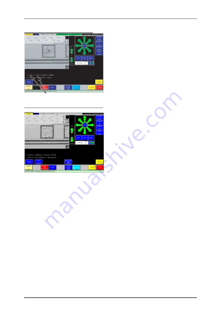
Probe mark position correcting screen
Amount of Needle Mark Position Correction
Die selecting screen for reconfirming probe
mark
<Site Change>
button:
For a multi-site probe card each stroke of this
button brings the view of die under the next site
probes; use this for selecting an appropriate die
group avoiding the already probe-contacted dice.
With the parameter “Feedback to Device Data?” in
[Needle Height Settings] set to ‘0: Yes’ (see Page
3-5), if the X or Y probe mark position correction
amount has exceeded ±50 µm, the error message
"Correct value for needle position is greater than 50
µm!! Push <DATA-IN> or <CANCEL> SW."
appears. Clear the alarm, push the button and
readjust the cross mark position to make the
amount within ±50 µm.
For the probe mark position correction, you can
choose any pad of any site (even a pad not
registered yet). So, check the probe marks over all
the sites and choose a representative probe mark
for the correction.
For confirming the probe marks after the correction,
push <Height Set Die Change> button twice at first.
The display changes to the screen shown lower left;
with Joy Stick set to INDEX mode, bring a wanted
die in the view. At this time, the indication of "Site
No." in the upper left corner is kept to "1", meaning
that the die thus chosen is contacted by Site No. 1
probes.
After the selection push <Data-in> button; the
display changes to the probe mark reconfirming
screen as shown upper left. Pushing <Exit> button
on the screen has Chuck driven to under the probe
card and the display shows the screen same to the
one after the contact height determination. For
putting probe marks on the pads again, push
Z-DRIVE switch once.
In order to reconfirm the probe marks, push <Image
Display Change> button; Chuck comes to below the
alignment camera again and the screen shows the pad
with the new probe mark on which the probe mark
position correction took place.
CAUTION:
When Chuck has returned to below the probe card and the display has become the manual
contact height adjusting screen, Joy Stick is operable only in INDEX mode. However, after
returning to the wafer map screen with <Data-in> button pushed there, Joy Stick becomes
operable in JOG or SCAN mode, too. If you have operated Joy Stick in JOG or SCAN mode in
the time after the probe mark position correction till putting probe marks with Z-DRIVE switch,
the probe marks after the correction may have displaced. When this has occurred, push
<Needle Height Change> button on the wafer map screen to call up the manual contact height
adjusting screen. Push <Data-in> button again there; this will cancel the Chuck travels with Joy
Stick other than the registered probe mark correction amounts.


