Installation of Teflon
®
liners for aluminum/
stainless steel in Euro quick-connect guns
1. Lay the torch out straight and remove the liner retaining nut at the wire feed end of
the torch cable. Remove the existing gun liner if fitted. If switching from a steel liner,
remove the swanneck and fit the appropriate brass neckliner for aluminum – stock
number B2440 for wires .024” to .040” (.6mm-1.0mm) or B4052 for wires .040” to
.052” (1.0mm-1.4mm) – as per instructions on pages 2 and 3. Replace the swanneck
with brass neckliner fitted.
2. Gently feed the plastic liner through the cable assembly until the liner bottoms out in
the neckliner collet. If unsure whether the liner is in the neckliner collet as far as it can
go, remove the swanneck, feed the liner through so that it protrudes 7-8 mm from the
body, taking care not to kink the liner. Replace the swanneck, inserting the protruding
end of the liner into the neckliner collet, and tighten down the swanneck locking ring.
Push the liner again to make sure it has bottomed in the neckliner collet.
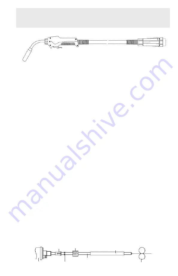
3. Refer to the diagram below: At the adaptor block end of the torch cable, slide the
brass collet and O-ring over the liner until they are located in the recess in the adap-
tor block; replace the liner retaining nut. DO NOT CUT THe LINeR yeT!
4. If the wire feed unit was previously set up for steel wire, it may be necessary to take
a pair of long-nosed pliers and remove the steel inlet guide from the central adaptor
installed in the front face of the wire feed unit.
5. With the plastic liner still protruding from the adaptor plug, feed the liner through the
inlet of the central adaptor until the adaptor plug on the torch is butted against the
central adaptor. Fasten into position with the plastic adaptor nut. Lift the feed rollers
of the wire feeder to enable the excess liner to pass through. Cut the liner, using a
sharp knife, so that it butts up to the feed rollers, thereby supplying support to the soft
wire immediately after it exits the drive rolls. If this is done correctly, “bird-nesting” in
the event of a wire jam will be prevented.
6. Remove the welding gun from the machine and ensure that the brass guide tube is 3
mm shorter than the protruding plastic liner (if not, cut accordingly). Slide the guide
tube over the liner and feed the liner (with the guide tube fitted) into the inlet in the
central adaptor; continue to feed through until the adaptor plug is butted against the
central adaptor, then tighten the plastic adaptor nut.
Note: Plastic liners with a diameter of 4.7 mm do not require a guide tube. (See
diagram below for correct location of parts.)
7. Reduce the wire hub tension by backing off the nut in the center of the hub until the
friction is only enough to stop the wire spool from spinning freely.
8. After confirming that the feed rolls are the correct size and type for the wire being
used, and that the wire is fed into the liner correctly, back off the wire feed roll pres-
sure until the feed rolls no longer feed the wire, then retighten slightly. Be cautious, as
too much pressure will deform soft wires such as aluminum and cause the wire to jam
in the contact tip.
7
Brass Guide Tube
Liner Retaining
Nut
Collet
Adaptor Plug
O-ring
(Prevents gas loss)
Liner
Wire Feed Roll
Содержание ALPHA 1
Страница 1: ...www binzel abicor com ABICOR ALPHA SERIES Instruction Manual ...
Страница 2: ......
Страница 23: ......


