EN - 16
BAL.0415.0 • 2018-10-22
6 Putting into operation
TIG cold-wire feeder
6.4.3 2-cycle and interval with torch for controlling the power source via the feed
Setting the wire feeder and welding current source to 2-cycle mode.
Move the rocker towards
T4
to switch on the wire feed and the welding current source.
On releasing the rocker, the welding process and the wire feed are stopped.
The wire feed can be delayed when starting welding using the parameter
dt
(0 – 3 sec.).
Wire retraction can be used when stopping welding. The wire retraction time is set using the parameter
rE
(off – 3 sec.).
The wire retraction feed rate is set using function
F2
.
The applicable parameter settings can be found in the following table:
6.4.4 4-cycle and interval with torch for controlling the power source via the feed
Setting the wire feeder and welding current source to 4-cycle mode.
Move the rocker towards
T4
to switch on the wire feed and the welding current source.
Move the rocker again to switch off the welding current source.
The wire feeder shut-down can be set on the 2nd or 4th cycle. Move or release the rocker towards
T2
to start or stop the
wire feed.
Stopping the wire feed in the 2nd cycle enhances the end quality of the welding process (wire stops sooner) and prevents
the wire from sticking in the weld pool. The setting is made using function
F6
(2 – 4).
The wire feed can be delayed when starting welding using the parameter
dt
(0 – 3 sec.).
Wire retraction can be used when stopping welding. The wire retraction time is set using the parameter
rE
(off – 3 sec.).
The wire retraction feed rate is set using function
F2
.
NOTICE
• A specially equipped intermediate cable assembly is required for this function.
Function
Description
Explanation of the setting process
dt
Wire feed delay time
Tab. 9 Display indicators after switching on on page EN-11
rE
Wire retraction time
Tab. 9 Display indicators after switching on on page EN-11
F2
Wire retraction feed rate
Tab. 10 Display indicators for advanced functions on page EN-13
T4
Rocker
Switch the welding current source on or off
Tab. 14
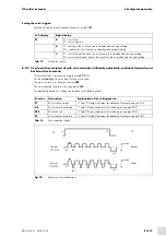
Settings for 2-cycle and 4-cycle mode
Fig. 11
Example of 2-cycle mode
T2
Motor
Motor
m/min
m/min
Normal
Interval
2T
t1
t2
ton
dt
tof
t=rE
dt
t=rE
NOTICE
• A specially equipped intermediate cable assembly is required for this function.

