background image


Device Functions


System Manual 2CKA000073B9795 

│27


Device Functions 


3.1 

Functions 


Door communication 


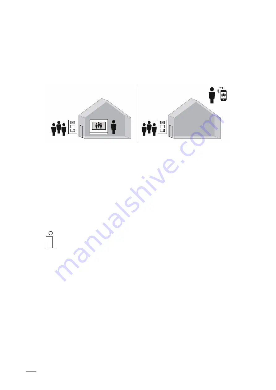
Fig. 13:  Door communication  


All visitors are received at outdoor stations. Depending on the outdoor station used, call the 
desired indoor station via modern or more classic methods such as bell buttons. 

The call is signalled at the desired indoor station. From here the call can be received and the 
door opened. The camera image is displayed directly at the indoor station, to ensure that you 
immediately see who is at the door. You can communicate with the visitor via the audio module. 
Any type assembly arrangement of modules is possible for an outdoor station due to the 
modular system.  

If you are not home at present, the visitor can leave you a message. 

The ABB-Welcome App turns your smartphone or tablet into a virtual indoor station while you 
are travelling. As is normal, you are informed about all visitors, talk to them and open the door 
for them.  


Note 

The creation and storing of photos as well as user data can infringe on personal 
rights!  
–  Ensure that the applicable legal provisions are adhered to when setting up 

and operating devices.  


Concierge function 

Calls can also be answered at a concierge station. Here the the same range of functions is 
available as for the indoor stations. 

The concierge can transfer the call to an indoor station or assign the access authorisation 
himself. 


Automatic door opener 

If necessary, the indoor station can be configured to allow visitors to enter automatically. During 
the set times the door opens automatically as soon as someone rings the bell. 


Содержание Welcome IP

Страница 1: ...System Manual 08 04 2019 ABB Welcome IP ...

Страница 2: ...port bases for mounting on desktop 20 2 4 5 Mounting possibilities 21 2 4 6 Mounting in hollow walls 21 2 4 7 Mounting in clinker facades 22 2 4 8 Mounting in insulated facades 22 2 4 9 Mounting with stiff LAN cables 24 2 5 Connection Connecting diagram 25 2 6 Prerequisites 25 2 7 Installation Data transmission 26 3 Device Functions 27 3 1 Functions 27 4 Commissioning 30 4 1 Overview of commission...

Страница 3: ...a transmission 56 5 2 1 Ethernet cable Ethernet network 56 5 2 2 Integration ABB free home 57 5 2 3 PoE planning Ethernet WLAN 58 5 3 Function test 60 5 4 IT protection 61 5 4 1 Early detection of risks 61 5 4 2 Glimpses into the private life 61 5 4 3 Foreign control of your house 61 5 4 4 Increase of safety 61 5 4 5 Minimisation of the risks 62 5 4 6 Password manager 63 5 4 7 Remote access 63 6 C...

Страница 4: ... the use of PoE switches A power supply via the local 230 V mains network is possible as an option Building automation The system has additional interfaces for the smooth integration into the building automation Connection of parallel networks The interlacing of several separate networks is carried out via IP gateways This is practical for example if you wish to connect the door system with a home...

Страница 5: ...with the topic read through all the relevant subchapters on this topic 1 3 Target group Qualifications of personnel 1 3 1 Installation commissioning and maintenance 1 3 2 Planning the system and the installation 1 4 Design lines This system manual serves for the technical planning of the simple to complex installations The different design lines with the respective special colours and shapes of th...

Страница 6: ... Power supply PoE switch Power supply Local Consumption Recording of power W IP touch 7 300 mA 27 VDC 8 1 IP touch 5 outdoor station 400 mA 27 VDC 10 80 Guard unit 85 mA 27 VDC 2 30 Smart Access Point Pro 375 mA 27 VDC 10 13 IP actuator 30 mA 27 VDC 0 81 Lift control 60 mA 27 VDC 0 405 Lift relays 300 mA 27 VDC 8 1 Table 1 Calculation of consumption ...

Страница 7: ...l output Example for the selection of a PoE switch Current A Power W per necessary port Number of devices Total output W IP touch 7 0 3 8 1 6 48 6 IP touch 5 outdoor station 0 4 10 8 1 10 80 Guard unit 0 085 2 295 1 2 30 Smart Access Point Pro 0 375 10 125 1 10 13 IP actuator 0 03 0 81 1 0 81 10 88 57 Table 2 Determination of total output of the devices to be connected Result Number of necessary p...

Страница 8: ...imeter areas Storey areas Apartment doors Basement garages Visitors call at the stations when they arrive For the door call there is also a voice output aside from the classic doorbell buttons The voice output can be activated as an option Outdoor stations are always available with video function Outdoor stations are available in the materials stainless steel and white and aluminium 1 2 3 4 5 6 7 ...

Страница 9: ... programmed as desired switching on lighting calling indoor station or protection unit Detection of door status Integrated lighting and automatic background illumination Transfer of all calls to the indoor station Guard unit Support of lift control Integrated RFID reader MIFARE DESFire Door opening via encrypzed IC or ID card News and advertising via 5 inch monitor Suitable for the disabled with i...

Страница 10: ...can leave you a message The indoor stations can also be used for communication within and between apartments and buildings The management software installed on the Smart Access Point can be used to administer which stations can call each other directly or be connected with each other by concierge stations The integrated blacklist can be used to specify which calls are blocked automatically For the...

Страница 11: ...nt prerequisite is an Internet connection Central operating field for DES CCTV AC and home automation KNX F H Video doorbell via IP camera LAN interface 1 2 1 1 Wi Fi interface 1 1 Remote firmware update Power supply PoE Local power supply unit Mounting Wall mounting Desktop mounting Call lists Receipt of alarm and emergency call SOS Triggering a fire alarm Support of surveillance from outdoor sta...

Страница 12: ...Overview of product range System Manual 2CKA000073B9795 12 2 3 3 System devices 2 3 4 5 1 Fig 3 System devices ...

Страница 13: ...ions Availability upon request More than 700 apartments Availability upon request If more than 700 apartments have to be managed via the system controller a very high computing performance is required In this case install the management software on a PC for example and use it as a system controller The PC version of the management software is available separately on a USB stick 2 IP actuator H8304...

Страница 14: ...stem If the home owner wishes to activate the lift control function a lift control module must be available Activation of the lift control function The home owner can call the lift prior to leaving the building and he can also call and authorise the access to the lift storey for visitors after opening the door During the communication from house to house the home owner can call and authorise the a...

Страница 15: ...nstallation are available separately in the corresponding size for each device The product is packed with accessories to guarantee a high quality installation Note Mounting boxes for surface mounting or flush mounted installation must be ordered additionally for the device The mounting box for flush mounted installation is always supplied as a set together with the associated flush mounted box ...

Страница 16: ... mounted installation The mounting box for flush mounted installation is always supplied as a set together with the associated flush mounted box Flush mounting box for outdoor stations size 1 3 size 1 4 size 1 5 size 2 3 3 Flush mounting box The flush mounted box serves as mounting accessory for plastering walls or facades The flush mounted box is installed prior to plastering The flush mounted bo...

Страница 17: ...Overview of product range System Manual 2CKA000073B9795 17 Sizes for the outdoor station mounting boxes Outdoor station Size 1 x 5 1 x 4 Outdoor station Size 1 x 3 2 x 3 ...

Страница 18: ...flush mounted installation Mounting boxes for flush mounted installation Outdoor station 1 x 5 1 x 4 1 x 3 2 x 3 41385 F xxx 41385 PB xxx 41384 F xxx 41384 PB xxx 41383 F xxx 41383 PB xxx 41386 F xxx 41386 PB xxx Mounting boxes for flush mounted installation Indoor station 42363 F xxx ...

Страница 19: ... 19 2 4 3 Mounting boxes for surface mounting Mounting boxes for surface mounted installation Outdoor station 1 x 5 1 x 4 1 x 3 2 x 3 41385 S xxx 41384 S xxx 41383 S xxx 41386 S xxx Mounting boxes for surface mounted installation Indoor station 42363 S xxx ...

Страница 20: ...20 2 4 4 Support bases for mounting on desktop Support base Indoor stationIP touch 7 42363 S xxx Support base Guard unit The Guard unit has been designed exclusively for mounting on desktops No additional accessories are required for mounting on the desktop ...

Страница 21: ...ation used into the facade The suitable template is enclosed with the box Dimensional drawings Note The encircling collar of the flush mounted box must rest on the facade Fig 5 Mounting instructions for the flush mounted housing Use the separately available hollow wall mounting set to anchor the flush mounted box in the cut out 83511 500 Fig 6 Cavity wall set 83511 500 ...

Страница 22: ...he cut out of the facade with the aid of the elongated holes You can fill the hollow spaces between the box and clinkers with PU foam Break out the holes in the corners angled at 45 Insert the extension tube of the PU foam and fill the cavities Note Use a low expansion foam to prevent foam from entering the flush mounted box If necessary use foam cleanser to remove the contaminations No additional...

Страница 23: ... existing cavities with suitable insulation material After the insulation and plastering 4 Carefully remove the plaster located over the box Note Ensure that a sufficient amount of plaster remains so that the hole can later be completely covered by the encircling collar of the flush mounted installation box 5 Insert the flush mounted installation box C into the flush mounted box and tighten it wit...

Страница 24: ...ush mounted boxes with these cables can be a problem A proven solution has been to use a flat LAN cable for the last short piece in front of the device and fit it to the actual LAN cable with a universal LAN module e g ABB0219 101 500 Fig 11 Adapter 0219 101 500 Note The flat LAN cable must be suitable for a power transmission via PoE from the transmission standard Cat5e ...

Страница 25: ...stem are listed in the following Network Own physical network or VLAN with Quality of Service QoS Setup of the active network components in Ethernet technology Minimum demands on the network 100Base Tx Consistent multicast network Wiring Structured wiring according to DIN 50173 1 2 2 3 3 4 4 Wiring at least Cat 5 5e Services in the network Abb 12 Switch with Routing Service A Switch without Routin...

Страница 26: ...al 2CKA000073B9795 26 2 7 Installation Data transmission Information about basic functions and principles of operation of the components for data transmission is available at Chapter 5 Information about planning and application on page 54 ...

Страница 27: ... are not home at present the visitor can leave you a message The ABB Welcome App turns your smartphone or tablet into a virtual indoor station while you are travelling As is normal you are informed about all visitors talk to them and open the door for them Note The creation and storing of photos as well as user data can infringe on personal rights Ensure that the applicable legal provisions are ad...

Страница 28: ...s into the network These can be displayed additionally for example during the door communication Multimedia player The indoor stations play video and audio files that are located on an inserted SD card Image files can be displayed as slide show or used as screen saver SD cards Type Micro SDHC Storage size 4 32 GB Speed class Class10 File system FAT32 Use a card that corresponds to the SDHC standar...

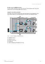
Страница 29: ...station always with you Integration into building automation The system can be smoothly integrated into automation systems such as free home or KNX Here all indoor stations serve simultaneously as control unit for the free home network Fig 14 Overview of integration into building automation 1 H82365 IP touch 7 2 H82364 IP touch 7 3 System Access Point 4 free home 5 Option Smartphone with ABB Welco...

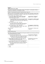
Страница 30: ...apter 6 Case studies on page 64 are selected detailed procedures based on standard situations Section 1 Preparing devices and assigning the physical addresses Detailed information on the system of the addresses see chapter 5 1 Adressing ABB Welcome IP devices networking connecting on page 54 There are two ways for assigning the addresses Assigning the physical addresses manually see chapter 4 2 Ph...

Страница 31: ... Functional The system controller Smart Access Point is called up later by a browser via the static IP address 10 0 0 1 After the login select the mode Residential The later IP address of system controller Smart Access Point must be determined on a router see chapter 4 5 1 Project import from ABB Welcome App on page 49 Stumbling blocks Xxxxx xxxxx see chapter 4 5 2 Add manually on page 51 Section ...

Страница 32: ...es are joined in the management software of the Smart Access Point system controller Call up the system controller again via the browser of the PC if there is no longer a connection Joining the device together The indoor stations are assigned to each outdoor station they are to communicate with ...

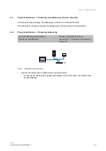
Страница 33: ...ressing is carried out via the indoor station 4 2 1 Physical addresses Preparing addressing For commissioning you are located in Section 1 Preparing the devices Overview of commissioning see chapter 4 1 Overview of commissioning on page 30 Fig 15 Preparation of commissioning 1 Connect the devices to the indoor station via a PoE switch As soon as the devices are supplied with voltage via the PoE sw...

Страница 34: ...g 16 Addressing station IP touch 7 or Guard unit The wizard is displayed after the device has booted up automatically and will guide you through the first setup If the device has already been setup the main menu is displayed directly To address the device perform the following steps 1 Follow the steps of the wizard for the first commissioning 2 Enter the address of the device in the technical menu...

Страница 35: ...e automatic boot up 1 2 Fig 17 Outdoor station without display Engineering mode To address the device perform the following steps 1 Activate Engineering mode After the LED icons 1 in the camera have stopped being lit up keep the top doorbell button pressed for 11 seconds In case of several bell spaces the first doorbell button below the audio shell 2 The LEDs flash green 2 Switch to the indoor sta...

Страница 36: ...itch to the engineering menu at the indoor station Start function Outdoor station settings The outdoor station is searched for automatically Address the outdoor station and save the entries 4 Restart the outdoor station The outdoor station is addressed ...

Страница 37: ...h display Engineering settings To address the device perform the following steps 1 Open the Entry code function in the standby mode 2 In window Password enter the following settings password The device switches automatically to window Settings On the password see the information at the end of this section 3 Open the Engineering settings function 4 In the area Engineering settings assign the physic...

Страница 38: ...ed for the first setup and changed to a different password It cannot be used as actual password Note If a wrong engineering password is entered 10 times within 5 minutes no further tries are possible for the next 5 minutes Password rule The password must not contain consecutively rising or falling numbers e g 123456 654321 and three consecutive identical numbers are also inadmissible e g 123444 66...

Страница 39: ... page 30 1 Fig 20 IP actuator Engineering mode To address the device perform the following steps 1 Activate Engineering mode After the device has booted press button Reset The LED flashes The flashing signals that the device is in Engineering mode If no entry is made within the next 5 minutes the device exits the Engineering mode automatically 2 Switch to the indoor station Fig 21 Addressing IP ac...

Страница 40: ...795 40 3 Switch to the technical menu at the indoor station Start function IP actuator settings The IP actuator is searched for automatically Address the IP actuator and save the entries 4 Restart the IP actuator The IP actuator is addressed ...

Страница 41: ...ew of commissioning see chapter 4 1 Overview of commissioning on page 30 On the rear side of each device are 2 stickers with the serial numbers of the device One of them is fitted with a QR code This is necessary for the preparation of the device with the ABB Welcome App To add the devices perform the following steps Fig 22 Configuration mode 1 Switch to Configuration mode in the ABB Welcome App ...

Страница 42: ...23 Start creation of the building structure 2 Add a building structure the ABB Welcome App if this has not yet been created 3 In the ABB Welcome App in the building structure switch into the room to which the device is to be added Fig 24 Adding devices ...

Страница 43: ... number The information of the device is stored in the project in the ABB Welcome App This information is transferred in a later step into the Smart Access Point for the commissioning process The device is prepared for commissioning in the management software 6 Prepare all additional devices in the same manner All devices are prepared for commissioning in the management software ...

Страница 44: ...ces into the system One mode must be selected for the connection with the PC during the course of the steps Residential mode The later IP address of system controller Smart Access Point must be determined on a router Functional mode The system controller Smart Access Point is called up by a browser via the static IP address 10 0 0 1 For this the IP address of the PC must be located in the same add...

Страница 45: ...e Fig 27 Entering the IP address in a browser 2 Call up the start page of system controller Smart Access Point in the browser For this enter the IP address in the address line of the browser The IP address is located next to the WLAN access data 3 Follow the steps of the wizard Select the matching mode during the course of the steps Residential or Functional see the introduction of the chapter Aft...

Страница 46: ... Connecting system controller with a PC Overview of commissioning see chapter 4 1 Overview of commissioning on page 30 The IP address of the connection must be put on the same area on the PC laptop as that of the device only required once Otherwise the Web browser does not establish a connection to the device Fig 28 Setting the IP address in the PC example Windows 10 ...

Страница 47: ... Dialogue field Connections is displayed 4 Open in dialogue field Characteristics 3 5 Mark in dialogue field Internet protocol Version 4 TCP IPv4 4 6 Open in dialogue field Characteristics 5 7 Activate in dialogue field Use the following IP address 6 8 Enter the correct IP address at IP address example 120 168 0 100 7 9 At Subnet mask Only enter a click 8 The address is located automatically 10 Co...

Страница 48: ...ning on page 30 Fig 29 Determining the IP address via router Determining the IP address with the example of a Fritz Box router Use the following steps to determine the IP address 1 Connect the device to the router with the determined IP address 2 Log into the router on the PC via a browser 3 Open the network connection LAN or WLAN in area Overview Connections 1 All devices connected with the route...

Страница 49: ...me router as the system controller Smart Access Point In this case the ABB Welcome App locates the available system controller Smart Access Point automatically Functional mode The smartphone is connected to system controller Smart Access Point via WLAN Here the smartphone must be located in the same address location 10 0 0 xx as system controller Smart Access Point Error source To upload the proje...

Страница 50: ...pload it into system controller Smart Access Point Fig 32 System controller Project selection for project import 4 On system controller Smart Access Point select the project to which the devices are to be added and confirm the project The upload of the project starts The upload can take several minutes depending on the scope ...

Страница 51: ...ing on page 30 Fig 33 Main menu Device Management Use the following steps to add devices manually 1 Connect a PC with system controller Smart Access Point and call up system controller Smart Access Point via a browser 2 Start the Device Management function in the main menu of system controller Smart Access Point 3 Select add devices All located devices are displayed 4 Enter the following data Devi...

Страница 52: ... see chapter 4 1 Overview of commissioning on page 30 Fig 34 Main menu Start search Use the following steps to search for devices automatically 1 Connect a PC with system controller Smart Access Point and call up system controller Smart Access Point via a browser 2 Start the Add manually function in the main menu of system controller Smart Access Point 3 Start the search All located devices are di...

Страница 53: ...or the door opener Here for example the bell on an outdoor station is specified that is to communicate with which indoor station Fig 35 Joining device together To join the devices perform the following steps 1 Connect a PC with system controller Smart Access Point and call up system controller Smart Access Point via a browser 2 Start the Device Management function in the main menu of system contro...

Страница 54: ...nciple of addressing 1 Buildings 2 Floors 3 Apartment 4 Device in an apartment The address of a device is principally the same for all devices The address consists of 4 parts Part 1 designates the building part 2 the floor part 3 the apartment on a floor and part 4 the device in a private apartment When buildings floors or apartments are added the address for the devices is counted upwards ...

Страница 55: ...73B9795 55 Building Address Floor Address Apartment Address Device Address Indoor station 1 999 01 63 01 32 01 08 Public outdoor station 000 999 01 64 Private outdoor station 1 999 01 63 01 32 01 64 Guard unit 1 32 Management Software IP actuator H8304 000 999 01 64 ...

Страница 56: ...re the structure of a general network that meets all requirements also in the long term is aimed at The cabling is divided into the areas of site cabling primary area vertical storey cabling secondary area and horizontal storey cabling tertiary area The areas can be planned and installed independent of each other The site cabling is the networking between different buildings From here the net is d...

Страница 57: ... Gbit s possible OWG are mainly used for the distribution between buildings This makes longer transmission distances possible It can also be used for the distribution in the building especially for the vertical storey distribution The transmission of the data between OWG and copper cables is made via media converters 5 2 2 Integration ABB free home Next to door communication the indoor stations ar...

Страница 58: ...vailability of the power supply any PSE device can be used It must only be ensured that the necessary performance class is supported PSE devices are usually Endspan devices such as PoE switches For the later integration of PoE loads into existing networks Midspan devices such as PoE injectors are often used The voltage is fed in from the last device before the load It can not be distributed by con...

Страница 59: ...ctions Here too the maximum cable length between two devices must nor exceed 100 m However it should be noted that a Cat 5e cable exhibits a higher generation of heat due to its low cable cross section This can among others have a negative effect on the reachable transmission range Compatibility with foreign devices The ABB Welcome IP devices are exclusively compatible with standardised PoE versio...

Страница 60: ...h devices are correctly interconnected Precise details for the connection of a device to the auxiliary power supply is available in the respective instruction manual of the device Signal test If the device does not receive a signal ensure that both ends of the data line are connected with a device that both devices are supplied with power and are switched on Whether the indoor station is correctly...

Страница 61: ... life As soon as the basic elements of privacy such as doors windows or cameras are connected with each other via the Internet comprehensive protection is of vital importance Especially when the user is travelling and can gain access to the surveillance cameras there is the danger that also third parties can read the data Also the trapping of simple control signals bears the risk of disclosing you...

Страница 62: ...ces should be protected against unauthorised dismantling 5 4 5 Minimisation of the risks Separate LAN WLAN network For building automation a separate LAN or WLAN network with its own hardware router switches etc should be used Provide an adequate WLAN cover Using safety mechanisms for IP networks Use anti virus software and firewall Encryption of wireless networks WPA2 or higher Use safe passwords...

Страница 63: ...ly used Apple Facebook PayPal and other Internet providers offer this option 5 4 7 Remote access Routing and IP tunnelling are not safe for use on the Internet since they use a protocol that is not encrypted No ports of routers are to be opened in the direction of the Internet this prevents KNX communication from becoming visible on the Internet For the remote access a VPN tunnel or the Living Spa...

Страница 64: ...h 5 outdoor station System controller Smart Access Point D0401 Indoor station IP touch 7 H8236 Indoor station Guard unit H8303 Auxiliary power supply Power supply YSM01 PS IP actuator H8304 IP actuator Lift control Lift control module YSM23 LC Lift control Lift control relay module 4825 Y Switch Commercially available Router Commercially available Network cable Power supply cable ...

Страница 65: ...ecome familiar with the topics Apartment Switch with PoE and Routing The PoE switch and routing are enabled in the apartment That is why no additional devices are necessary for this function The indoor station in the version is intended for LAN connection P E o Fig 37 Overview Apartment Switch with PoE and Routing PoE LAN GND DC LAN LAN LAN LAN LAN LAN Fig 38 Connection Apartment Switch with PoE a...

Страница 66: ...pable in the apartment That is why an additional power supply is required The indoor station in the version is intended for LAN connection Fig 39 Overview Apartment Switch without PoE LAN LAN GND DC LAN GND DC N L 100 240 V GND DC GN D DC LAN LAN LAN LAN Fig 40 Connection Apartment Switch without PoE ...

Страница 67: ...uting capable in the apartment That is why an additional router is required The indoor station in the version is intended for LAN connection P E o Fig 41 Overview Apartment Switch without routing LAN LAN LAN PoE LAN GND DC LAN LAN LAN LAN LAN LAN LAN Fig 42 Connection Apartment Switch without routing ...

Страница 68: ...s made via a router The router is not PoE capable That is why an additional power supply is required The indoor station in the version is intended for LAN connection Fig 43 Overview Apartment no switch router no PoE LAN LAN GND DC LAN GND DC N L 100 240 V GND DC GN D DC LAN LAN LAN LAN Fig 44 Connection Apartment no switch router no PoE ...

Страница 69: ...e necessary for this function The indoor station in the version is intended for WLAN connection This for example makes a later extension possible for access control for inputs This is activated via WLAN P E o Fig 45 Overview Apartment indoor station with WLAN LAN LAN LAN PoE LAN GND DC LAN LAN LAN LAN LAN LAN LAN 24V DC Fig 46 Connection Apartment indoor station with WLAN ...

Страница 70: ... with an automatic door opener That is why an IP actuator is required which accepts the digital opening command and switches the door opener Also the light in a room is to be switched via the IP actuator If the light is to be switched in additional rooms via IP actuators additional actuators are required one each for 2 switching connections P E o Fig 47 Overview Apartment with actuator PoE LAN GND...

Страница 71: ...illustrated in the following Multifamily house Switch with PoE and Routing In the multifamily house the switch is PoE and routing capable That is why no additional devices are necessary for this function The indoor station in the version is intended for LAN connection Fig 49 Overview Multifamily house Switch with PoE and Routing ...

Страница 72: ...Case studies System Manual 2CKA000073B9795 72 Fig 50 Connection Multifamily house Switch with PoE and Routing ...

Страница 73: ...ding construction project with numerous apartments and separate safety lift Task The door communication is to be carried out via ABB Welcome IP in a large residential building construction project The lifts are to be connected with it A separate safety lift is to be controlled via an own ABB Welcome IP system ...

Страница 74: ...Case studies System Manual 2CKA000073B9795 74 PoE PoE Separate Safety Lift PoE PoE PoE Abb 51 Residential building construction project with numerous apartments and separate safety lift ...

Страница 75: ...ual 2CKA000073B9795 75 LAN LAN LAN PoE LAN LAN LAN LAN PoE LAN LAN LAN LAN GND D C N L 100 240 V DC LAN LAN LAN LAN PoE LAN LAN LIFT 01 LIFT 02 LAN LAN LAN POE LAN LAN LAN LAN LAN Fig 52 Connection Apartments of the building ...

Страница 76: ... 1 1 N C 1 1 N O 1 1 C O M 1 0 N C 1 0 N O 1 0 C O M 9 N C 9 N O 9 R e l a y O U T 9 1 6 G ND DC LB GN D LA 1 2 3 4 5 O N 1 2 3 4 5 6 7 8 I N D C G N D I N G N D L B L A S t a t u s P o w e r N O 1 N C 1 C O M 1 N O 2 N O 2 C O M 2 N O 3 N C 3 C O M 3 N O 4 N C 4 C O M 4 N O 5 N C 5 C O M 5 N O 6 N C 6 C O M 6 N O 7 N C 7 C O M 7 N O 8 N C 8 C O M 8 R e l a y O U T 1 8 C O M 1 6 N C 1 6 N O 1 6 C ...

Страница 77: ... 4 C O M 4 N O 5 N C 5 C O M 5 N O 6 N C 6 C O M 6 N O 7 N C 7 C O M 7 N O 8 N C 8 C O M 8 R e l a y O U T 1 8 C O M 1 6 N C 1 6 N O 1 6 C O M 1 5 N C 1 5 N O 1 5 C O M 1 4 N C 1 4 N O 1 4 C O M 1 3 N C 1 3 N O 1 3 C O M 1 2 N V 1 2 N O 1 2 C O M 1 1 N C 1 1 N O 1 1 C O M 1 0 N C 1 0 N O 1 0 C O M 9 N C 9 N O 9 R e l a y O U T 9 1 6 G ND DC LB GN D LA DC LAN LAN LAN LAN LAN PoE LAN GND DC N L 100 ...

Страница 78: ...y network capable devices with current via an existing data connection Only one cable is required for the transmission of the current and data PSE Power Sourcing Equipment Devices for the infeed of PoE E g PoE switches PD Powered Device Device that is supplied via PoE QoS Quality of Service Optimisation of connection through automatic prioritisation of applications Routing A device a computer for ...

Страница 79: ...Notes System Manual 2CKA000073B9795 79 8 Notes ...

Страница 80: ...ormation on the manual 5 Installation 26 Integration of ABB free home 57 Introduction to ABB Welcome IP 4 IP actuator 39 IP touch 7 10 34 IT protection 61 IT safety 61 J Joining device together 31 53 L Legend 64 Linking devices 53 M Management software Linking devices 53 Manual 5 Minimisation of the risks 62 Mounting accessories 15 Mounting boxes for flush mounted installation 18 Mounting boxes fo...

Страница 81: ...g 58 PoE switch criteria 7 PoE switch selection 7 Preparing addressing 33 Prerequisites 25 Private apartment 65 Project import from the ABB Welcome App 31 49 Q Qualification of personnel 5 R Remote access 63 Residential building construction project 73 S Stiff LAN cables 24 Support bases for mounting on desktop 20 System devices 12 T Target group 5 ...

Страница 82: ...roup PO box 58505 Lüdenscheid Freisenbergstraße 2 58513 Lüdenscheid www BUSCH JAEGER com info bje de abb com Central sales service Tel 49 2351 956 1600 Fax 49 2351 956 1700 Copyright 2019 Busch Jaeger Elektro GmbH All rights reserved 2CKA000073B9795 ...

Отзывы: