


- 98 -
UMC100-FBP
Universal Motor Controller
UMC100-FBP
Technical Description
FieldBusPlug / Issue: 03.2012
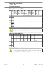
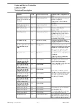
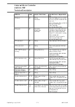
Icon
Meaning
i
Warnings available. Go into submenu Maintenance/Service->Diagnosis->Present Warn-
ings to find out the reason for the warning.
Motor stopped
,
Motor running forwards / fast forward
,
Motor running backwards / fast backwards
LOC
Local control mode 1/2 active
REM
Remote (auto) control mode active
Parameters unlocked / locked: If parameters are locked (indicated with the closed lock in
the icon bar) they cannot be changed either by the fieldbus or using the panel. To change
parameters you have to unlock them first. If password protection is enabled the pass-
word has to be typed in first before a parameter can be changed.
°C
Cooling time running. Motor cannot be started until the cooling time is over.
t
1) Reverse lockout time is running.
2) The motor cannot be started in opposite direction until the reverse lockout is over.
3) The pause time of the number of start limit function is running
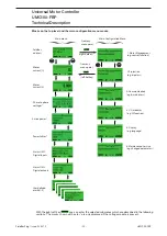
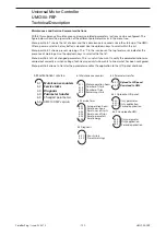
Pressing the up/down keys brings you to the next/previous menu on the same level. Pressing Menu en-
ters the first menu level. Pressing Cntrl brings you into the motor control menu.
The figure on the next page shows the top level menu structure and the main configuration menu.
The Menu Tree
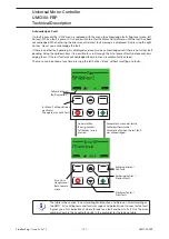
If you press
you enter the main configuration menu. The parameters are organised into groups as
described in the section "Parameters and Data Structures on a Fieldbus->Parameter Organisation" and
as shown in the diagram on the following page.
The scroll bar on the right indicates the present location in a configuration menu with several menu items.
On the top of the mask the active menu name (parent menu) is shown.
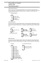
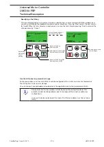
Monitoring Status Information
On the top level of the menu tree which is entered after powering on, several information masks show the
overall status of the UMC and connected IO. To switch between the different masks, use the scroll up or
scroll down keys. The LCD is split into the following different logical areas:
•
Header: At the top of the LCD the tag name or the submenu title is shown.
•
Main Area: Main display area to display process data or configuration data etc.
•
Icon Line: At the bottom of the LCD the actual function of the hot keys (left / right) is shown. In the
middle further status information is displayed as icons. The table below shows the different icons and
their meaning.
Main area to display
process values etc ...
Header: e.g. tag name
Status Icons Right hot key
function
Left hot key
function
Icon bar, hot keys
Содержание UMC100-FBP
Страница 1: ...Technical Description Universal Motor Controller UMC100 FBP ...
Страница 8: ... 8 UMC100 FBP Universal Motor Controller UMC100 FBP Technical Description FieldBusPlug Issue 03 2012 ...
Страница 36: ... 36 UMC100 FBP Universal Motor Controller UMC100 FBP Technical Description FieldBusPlug Issue 03 2012 ...
Страница 90: ... 90 UMC100 FBP Universal Motor Controller UMC100 FBP Technical Description FieldBusPlug Issue 03 2012 ...
Страница 94: ... 94 UMC100 FBP Universal Motor Controller UMC100 FBP Technical Description FieldBusPlug Issue 03 2012 ...
Страница 108: ... 108 UMC100 FBP Universal Motor Controller UMC100 FBP Technical Description FieldBusPlug Issue 03 2012 ...
Страница 154: ... 154 UMC100 FBP Universal Motor Controller UMC100 FBP Technical Description FieldBusPlug Issue 03 2012 ...
Страница 156: ... 156 UMC100 FBP Universal Motor Controller UMC100 FBP Technical Description FieldBusPlug Issue 03 2012 ...
Страница 157: ......


