


- 25 -
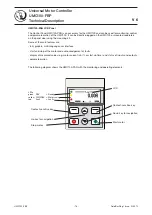
UMC100-FBP
Universal Motor Controller
UMC100-FBP
Technical Description
FieldBusPlug / Issue: 03.2012
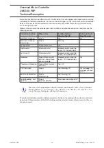
Type /
Korc-
type
Recom-
mended-
current
range [A]
Current
factor
(Default
= 1.0)
Secondary
current
range
[A]
Factor to be
set in the
UMC (e.g.
via LCD
panel)
Hole area
WxH
1)
(figures in mm)
Link kit (bar) type
for contactor
(Order code see
chapter 6.)
UMC100
alone
0.24-63
1
-
100
(default)
11 (diameter)
-
4L185 R/4
60-185
46.2
1.3-4
4620
22x28
DT450/A185 ->
AF145, AF185
4L310 R/4
180-310
77.5
2.3-4
7750
22x28
DT450/A300 ->
AF210-AF300
5L500 R/4
300-500
125
2.4-4
12500
41x22
DT500AF460L
2)
->AF400, AF460
5L850 R/4
500-850
212.5
2.4-4
21250
41x22
DT800AF750L
2)
->
AF580, AF750
1)
Wire size has to be fixed acc. to IEC/EN 60204
2)
Link kits for star-delta starter (others see catalogue)
If current transformers of other suppliers are used the table above may serve as a
calculation basis for the current factor.
Example: Type 5L500 R/4 means: Primary 500 A, secondary 4 A, current factor 125.
In the UMC to real motor current has to be set e.g. 500A.
Related parameter:
Current Factor, I
e1
, I
e2
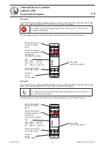
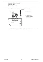
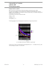
Operation Details for Motors with Small Set Currents
When using a UMC100-FBP in an environment with very strong magnetic fields and
a small set current at the same time, the current measurement can deviate a few
percent from the real current. Therefore the displayed motor current is too high and
an overload trip occurs too early.
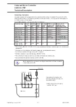
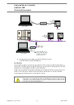
Very strong magnetic fields can originate from a contactor directly mounted beside
the UMC100, closely passing current links or stray fields caused by large transform-
ers. When observing the effect, the distance between the UMC100 and the contac-
tor shall be increased to about 5 cm or the UMC100 shall be rotated by 90 degrees
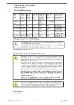
or the motor wires shall be looped through the UMC100 two to five times.
When looping the motor wires multiple times, the parameter
Current Factor
must be
adjusted according the number of loops. I.e. the parameter must be set to two if the
wires are looped through the UMC100 two times. Two to five loops are supported.
The displayed current and the current transmitted over the fieldbus are automatically
corrected by the UMC100.
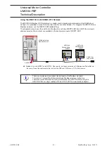
Please note that the adaptation of the current factor for
√
3 circuits and multiple
loops through the UMC100 are not possible at the same time.
Via fieldbus also higher values than five e.g. six can be set. The UMC100 ignores
such values and creates a parameter fault. Values above 100 are possible and used
in combination with external current transformers (see previous page).
Related parameters:
•
Current Factor
Содержание UMC100-FBP
Страница 1: ...Technical Description Universal Motor Controller UMC100 FBP ...
Страница 8: ... 8 UMC100 FBP Universal Motor Controller UMC100 FBP Technical Description FieldBusPlug Issue 03 2012 ...
Страница 36: ... 36 UMC100 FBP Universal Motor Controller UMC100 FBP Technical Description FieldBusPlug Issue 03 2012 ...
Страница 90: ... 90 UMC100 FBP Universal Motor Controller UMC100 FBP Technical Description FieldBusPlug Issue 03 2012 ...
Страница 94: ... 94 UMC100 FBP Universal Motor Controller UMC100 FBP Technical Description FieldBusPlug Issue 03 2012 ...
Страница 108: ... 108 UMC100 FBP Universal Motor Controller UMC100 FBP Technical Description FieldBusPlug Issue 03 2012 ...
Страница 154: ... 154 UMC100 FBP Universal Motor Controller UMC100 FBP Technical Description FieldBusPlug Issue 03 2012 ...
Страница 156: ... 156 UMC100 FBP Universal Motor Controller UMC100 FBP Technical Description FieldBusPlug Issue 03 2012 ...
Страница 157: ......


