I N S TA L L AT I O N , O P ER AT I O N A N D M A I N T EN A N C E M A N UA L
16
Additional features include provision for padlock, when maintenance is required.
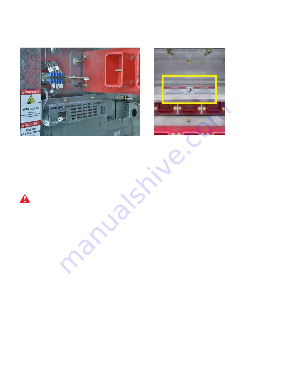
Truck operated contact
The TOC interacts with the position of the contactor, either “CONN.”, “DISCONN.” or intermediate positions.
Note: TOC are factory calibrated, no further adjustment is necessary.
Line side shutter
The contactor compartment features a mechanical shutter lock to prevent access to the line side bus when the
contactor is not in the compartment.
1. Use a Lift Truck to move the contactor to the height of the compartment.
2. Insert the tray guides of the Lift Truck in position in the compartment slots.
3. Release the contactor of the tray with the front hand grips and slide them firmly to the compartment until reach
the slots located on the rails of the compartment.
4. Release Lift Truck.
At this point the Contactor is not connected to the load side bus. The position indicator is “DISCONN.”
(extracted) and the status indicator is “OPEN”.
The automatic secondary pins are connected to the contactor control board, which can close the contactor for
testing in the status “CLOSED”.
Contactor mounting in compartment
The contactor is located outside the compartment ready to be inserted.
Fig. 14 TOC
Fig. 15 Line side shutter
—
Contactor compartment operation
Do not attempt to deactivate the shutter system. It only operates when the contactor is in the compartment.
Hazardous voltage can cause electrical shock and burns. Disconnect power, then earth and short-circuit
before accessing for any components in this area.
DANGER
NOTICE
Before putting the contactor into the contactor compartment, place the automatic secondary at its initial
position (at the front of the compartment).
Содержание SafeGear MCC
Страница 2: ... Medium voltage SafeGear Motor Control Center controlling energy for a safe world ...
Страница 28: ...25 SAFEGEAR MOTOR CONTROL CENTER ARC RESISTANT METAL CL AD CONSTRUCTION in mm General dimensions ...
Страница 37: ...INSTALL ATION OPER ATION AND MAINTENANCE MANUAL 34 6 Procedure 4 3 2 1 03 4 3 ...


