


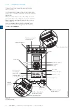


1SFC132081M0201 | Installation and commissioning manual |
Quick start
13
INFORMATION
The ground is not a protective ground, it is a
functional ground. The maximum length of the
ground cable is 0.5 m. Connect the ground cable
to the installation plate were the Softstarter is
attached. The installation plate must also be
grounded.
INFORMATION
Do not use functional ground in IT-networks, commonly
found in for instance marine applications.
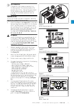
6.
Look at the diagram,
see
Figure 2.7,
and connect
the start/stop circuits: terminal 13, 14, 18, 19 and
20/21, with the internal 24 V DC terminal. When
you use internal 24 V DC (terminals 20 or 21), the
terminals 18 and 19 must be connected to each
other. For external control circuit voltage,
see
chapter
5.1.2.3 Start and Stop - terminals
13, 14, 18, 19, 20, 21
.
WARNING
Use 24 V DC only when you connect terminal 13, 14,
15, 16 and 17. Other voltages can cause damage
to the Softstarter and the warranty will no longer be
valid. For more information about terminal 15, 16 and
17, see
chapter
5.1.2.4 Programmable inputs -
terminals 15, 16 and 17
.
7.
Connect terminals 4, 5, 6, 7, 8, 9, 10, 11 and
12 to use the signal output relays. These are
potential-free contacts for maximum 250 V AC,
1.5 A AC-15 and 30 V DC, 5 A DC-12.
See
Figure 2.5.
8.
Make sure that the operation voltage and control
supply voltage agree with the Softstarter ratings.
9.
Set the control supply voltage switch to ON.
10.
The green Ready LED is constant lit if the following
conditions are fulfilled:
- Control supply voltage is detected
- Mains three phase voltage is detected
- Mains frequency is within range (40-72Hz)
- Motor connection is detected
- Phase sequence is detected
- No events are active
- Enable signal is active
- If the max nbr of starts per hour function is
enabled and set to stop manual or stop automatic,
the remaining time to start counter (which can be
shown in the HMI homeview) has to be zero
Otherwise the ready LED is flashing,
see Figure
2.6.
11.
The language settings appear on the screen.
Select your language and push the selection soft
key “OK”. The HMI now downloads the language
data from the Softstarter. This can take some
minutes. When this is done the HMI shows the
Home view.
12.
Configure applicable parameters as given in
chapter
7 Functions
or use the assistants as
given in
chapter
2.2 Configuration
.
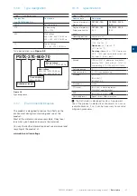
Figure 2.4
Functional ground, terminal 22
1SFC132081M0201
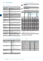
Figure 2.7
Circuit diagram (Fuse and contactor version)
22
L1
L2
L3
N
KM1
1L1 3L2 5L3
2T1 4T2 6T3
U
V
W
19 20
18
15 16 17
14
13
2
1
21
M
3
Stop
Star
24 V DC
t
L N
12
11
10
9
8
7
6
5
4
22
20
14
18 19
13
Start
Stop
1SFC132081M0201
Figure 2.5
Circuit diagram ( MCCB version)
22
L1
L2
L3
N
1L1 3L2 5L3
2T1 4T2 6T3
U
V
W
19 20
18
15 16 17
14
13
2
1
21
22
M
3
Stop
Star
24 V DC
t
L N
12
11
10
9
8
7
6
5
4
22
20
14
18 19
13
Start
Stop
1SFC132081M0201
Figure 2.6
Flashing “Ready” LED
PSTX
L
100-250V
50/60 Hz
K4
K4
K4
Start Stop Reset In1 In2 DGND DND +24V GND
N
1SFC132081M0201
2
Содержание PSTX Series
Страница 1: ...1SFC132081M0201 Softstarters Type PSTX30 PSTX1250 Installation and commissioning manual...
Страница 4: ......
Страница 6: ......
Страница 10: ...10 Introduction Installation and commissioning manual 1SFC132081M0201 1...
Страница 16: ...16 Quick start Installation and commissioning manual 1SFC132081M0201 2...
Страница 29: ...1SFC132081M0201 Installation and commissioning manual Description 29 3...
Страница 30: ...30 Description Installation and commissioning manual 1SFC132081M0201 3...
Страница 36: ...36 Installation Installation and commissioning manual 1SFC132081M0201 4...
Страница 50: ...50 Connection Installation and commissioning manual 1SFC132081M0201 6...
Страница 72: ...72 Human machine interface HMI Installation and commissioning manual 1SFC132081M0201 6...
Страница 143: ...1SFC132081M0201 Installation and commissioning manual Functions 143 7...
Страница 144: ...144 Functions Installation and commissioning manual 1SFC132081M0201 7...
Страница 148: ...148 Communication Installation and commissioning manual 1SFC132081M0201 8...
Страница 156: ...156 Maintenance Installation and commissioning manual 1SFC132081M0201 9...
Страница 168: ...168 Troubleshooting Installation and commissioning manual 1SFC132081M0201 10...
Страница 176: ...176 Wiring and application diagrams Installation and commissioning manual 1SFC132081M0201 11...
Страница 181: ...1SFC132081M0201 Installation and commissioning manual Third party licenses 181 12...
Страница 183: ...1SFC132081M0201 Installation and commissioning manual Revision 183 13...
Страница 187: ...1SFC132081M0201 Installation and commissioning manual Index 187 14...