


19
18
15
16
7
8
9
10
12
11
15
16
27
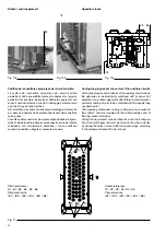
Fig. 8
Nella parte fissa sono montati i seguenti componenti:
– le guide (15) per il carrello;
– gli otturatori (18) di segregazione dei contatti fissi di seziona-
mento disposti all’interno dei monoblocchi ed i cinematismi di
azionamento delle segregazioni (16);
– il blocco meccanico che impedisce di inserire l’interruttore se
il sezionatore di terra è chiuso o di chiudere il sezionatore di
terra se l’interruttore è inserito (27).
Sul retro della parte fissa sono presenti i monoblocchi isolanti
(14) per i collegamenti di potenza.
The fixed part houses the following components:
– truck guides (15);
– segregating shutters (18) of the fixed isolating contacts inside
the monoblocks and the shutter operating mechanisms (16);
– mechanical lock for preventing either circuit-breaker racking in
when the earthing switch is closed or earthing switch closing
if the circuit-breaker is connected (27);
The insulating monoblocks (14) for the power connections
are on the rear of the fixed part.
5.4. Interblocchi/blocchi
•
Le manovre devono essere effettuate con la nor-
male forza di azionamento (non superiore a 200 N)
utilizzando esclusivamente le apposite leve.
Se risultassero impedite, non forzare gli interblocchi
meccanici e verificare la correttezza delle manovre.
•
I blocchi possono essere azionati con una forza
massima di azionamento di 400 N, utilizzando gli
appositi attrezzi di manovra.
I blocchi usati nelle parti fisse sono meccanici ed elettrici con
microinterruttori che danno continuità o interrompono il circuito.
Quelli meccanici si suddividono in:
– blocchi di forza;
– blocchi di impedimento;
– blocchi elettromeccanici;
– blocchi di sicurezza (lucchetti/chiavi).
I blocchi previsti sono quelli indicati nella seguente tabella.
5.4. Interlocks/locks
• The operations must be carried out using normal
operating force (not more than 200 N) only using
the special levers.
Should the operations be prevented, do not force
the mechanical interlocks and check that the ope-
rations are correct.
• The locks can be activated with a maximum force
of 400 N, using the special operating tools.
The locks used in the fixed parts are mechanical and electrical
with microswitches for circuit continuity or interruption.
The mechanical locks are divided into:
– force locks;
– prevention locks;
– electromechanical locks;
– safety locks (padlocks/keys).
PowerCube modules can be equipped with the locks shown in
the following table.
!
!
Содержание PowerCube PB/F
Страница 2: ......
Страница 23: ...21 6 2 4 2 6 5 3 1 2 3 4 5 6 7 1 Fig 9a Fig 9b Fig 9 ...
Страница 39: ......


