


MANUAL MOTOR STARTER GUIDE
APRIL 19
61/80
7.2.8 Defined acceptance criteria
Failure of components under fault conditions can lead to safety concerns for personnel working in close proximity to
electrical equipment. To outline what constitutes a pass, the harmonized UL 60947-4-1 and CSA C22.2 No.60947-4-1
standards define acceptance criteria for these components. Several criteria exist for all devices:
−
The short-circuit protective device successfully interrupts the fault
−
The enclosure door has not blown open, and it remains possible to open it manually
−
No damage to, or separation between, the conductors and the terminals
−
No damage to the insulating bases of live parts, and no access to current carrying parts
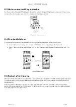
For Combination Motor Controllers, the included circuit-breaker, switch, or manual motor starter should be capable
of being manually operated, and should not be damaged, exposing conductive parts.
In addition to the above criteria, a distinction is made between two types of coordination: Type 1 and Type 2. This
pertains to the suitability of components for continued service following a fault.
7.2.8.1 Type 1 coordination
Type 1 coordination allows some components, such as the controller and overload protection device, to sustain dam-
age such that they become inoperable following a short-circuit fault. This coordination type requires that these
components are replaced before re-commissioning.
7.2.8.2 Type 2 coordination
Type 2 coordination requires that no damage to the overload protection and other components occurs, with the ex-
ception that the contacts of the contactor or starter are allowed to be welded. This welding must be easily separated
by manual effort (e.g. with a screwdriver). Both the overload tripping performance and controller switching capabili-
ties are verified following the short-circuit test.
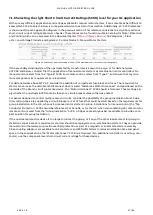
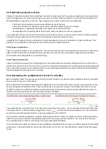
7.2.9 Calculating the available fault current for a facility
What rating do I need? The necessary short-circuit current rating for any device is determined based on the available
fault current at its point of installation.
Most industrial and commercial buildings are supplied by one or more transformers proving incoming power to the
facility. Using rated information from these transformers, it is possible calculate the available fault current for any
installation within the building. UL 508A provides the following formulas for determining available fault current in
circuits containing transformers with isolated secondary windings.
Available fault current beyond single-phase transformers
Available fault current beyond 3-phase transformers
𝐼𝐼
𝑠𝑠𝑠𝑠
=
�𝑘𝑘𝑘𝑘𝑘𝑘
× 1000
𝑘𝑘
𝑠𝑠𝑠𝑠𝑠𝑠𝑠𝑠𝑛𝑛𝑠𝑠𝑠𝑠𝑟𝑟𝑠𝑠
�
𝑍𝑍
%
𝐼𝐼
𝑠𝑠𝑠𝑠
=
� 𝑘𝑘𝑘𝑘𝑘𝑘
× 1000
𝑘𝑘
𝑠𝑠𝑠𝑠𝑠𝑠𝑠𝑠𝑛𝑛𝑠𝑠𝑠𝑠𝑟𝑟𝑠𝑠
×
√
3
�
𝑍𝑍
%
√
3
≈
1.732
The available fault current directly at a transformer’s secondary terminals
𝐼𝐼
𝑠𝑠𝑠𝑠
can be calculated from the transformer
full-load current
𝑘𝑘𝑘𝑘𝑘𝑘
, the secondary voltage line-to-line
𝑘𝑘
𝑠𝑠𝑠𝑠𝑠𝑠𝑠𝑠𝑛𝑛𝑠𝑠𝑠𝑠𝑟𝑟𝑠𝑠
and the transformer impedance
𝑍𝑍
%
. For transform-
ers with an unmarked impedance, this can be assumed to be 2.1 % (0.021
Ω
).
Let’s consider a facility supplied by a 3-phase, 3000 kVA transformer with an isolated secondary winding producing
480 V AC line-to-line, and with a marked impedance of 5.75%. Using the formula above, we can calculate the maxi-
mum available fault current for this facility to be just under 63 kA (62.755 A).
Since this calculation does not account for any additional impedance from the wires, and also assumes infinite utility
source power, the calculated value can be assumed to be “worst-case” for any installation supplied from this power
source.