


MANUAL MOTOR STARTER GUIDE
APRIL 19
50/80
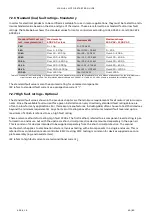
For accessories:
SK1, HK1, HKF1
M3.5
0.8 ... 1.2 Nm / 7 Ib.in
ø 5.5 mm
Pozidriv
No. 2
1/2 x 1 ... 1.5 mm
2
1/2 x 0.75…1.5 mm
2
1/2 x AWG 16…14
1/2 x 0.75…1.5 mm
2
8 mm
UA1, AA1
M3.5
0.8 ... 1.2 Nm / 7 Ib.in
ø 5.5 mm
1/2 x 1…4 mm
2
1/2 x 0.75…2.5 mm
2
1/2 x AWG 16…14
1/2 x 0.75…2.5 mm
2
S1-Mx-25
M3.5
2.5 Nm / 22 Ib.in
ø 5.5 mm
1 x 6…25 mm
2
1x AWG 10…4
1 x 6…25 mm
2
1x AWG 10…6
10 mm
S1-Mx-35
M8
4.5 Nm / 40 Ib.in
Hexa-
gon 4
1 x 100…35 mm
2
1x AWG 8…2
1 x 100…35 mm
2
1x AWG 8…2
12 mm
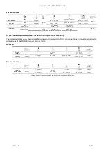
Table 16: Connection cross sections for screw connection technology for accessories.
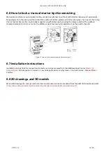
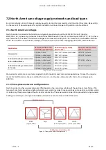
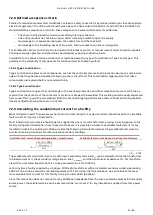
6.2.2.2 Connection cross sections for push-in spring terminal technology
The following tables show the permissible conductor cross-sections for main connections and auxiliary conductor
connections of the MS132K manual motor starter:
MS132-K:
MS132-K
(Push-in)
1 ... 2.5 mm
2
1 … 6 mm²
AWG 10 … 8
1 … 4 mm²
1x 1 … 4 mm²
2x 1 … 2.5 mm
12 mm
MS132 -K
(Spring)
ø 3 mm
x 0.5 mm
1 ... 2.5 mm
2
0.5 ... 4 mm
2
1/2 x 0.5 ... 4 mm
2
1x 0.5 … 4 mm²
2x 0.5 … 2.5 mm²
12 mm
For accessories:
SK1, HK1, HKF1
(Push-in)
1 ... 2.5 mm
2
1 … 2.5 mm²
AWG 14
1 ... 2.5 mm
2
1 … 1.5 mm²
10 mm
SK1, HK1, HKF1
(Spring)
ø 3 mm
x 0.5 mm
1 ... 2.5 mm
2
1 ... 2.5 mm
2
AWG 20 … 14
0.5 ... 2.5 mm
2
0.5 … 1.5 mm²
10 mm
Table 17: Connection cross sections for push-in spring terminal technology.