


MANUAL MOTOR STARTER GUIDE
APRIL 19
48/80
6. Installation and commissioning
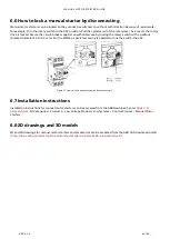
6.1 Mounting
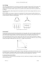
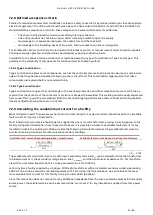
Manual motor starters can be mounted as follows:
−
Fixed on a 35 mm top hat rail according to DIN EN 60715 (35 x 15 or 35 x 7.5 mm).
−
Mounted using a screw fixing on a wall/panel. Manual motor starters can be fastened to the wall/panel using
screws. MS116/MS132 manual motor starters require an additional accessory.
Figure 29: Mounting of a manual motor starter.
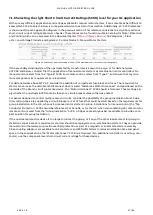
6.1.1 Mounting position and minimum distances
When mounting the manual motor starters, keep the following clearances to grounded or live parts and insulated
conduit ducts according to IEC 60947-2:
−
Single installation: there must be no directly attached contactor and there is a minimum gap of 9 mm to the
left and to the right.
−
Group installation: the contactor must be mounted directly or the gap to the left or the right must be less
than 9 mm.
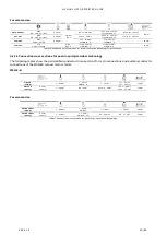
6.1.1.1 Mounting position
Mounting positions 1 until 6 are permitted for manual motor starters.
Mounting:
Dismantling:
Pos. 1
Pos. 3
Pos. 2
Pos. 4
Pos. 1
±
30°
Pos. 5
Pos. 6
Figure 30: Mounting position of a manual motor starter.