Содержание KD-10

Страница 1: ...rnal Connec tions Fault detectors are used to supervise the trip circuit for those applications where line side potentials are used or loss of potential supervision is desired Otherwise undesired tripping may occur on line os cillations or loss of potential The cylinder type KC 2 or KC 4 relay 2 8 amperes is recommended The plunger or other magnetic attraction type relays e g a three unit SC relay...

Страница 2: ...een taps are 0 03 09 and 06 The auto transformer makes it possible to expand the basic range of T ohms by a multiplier of Therefore any relay ohm setting can be made within 1 5 percent from the desired value by combining the compensator taps T TAB and TBC with the au to transformer taps S and M SA and MA and SC and MC See Tables I II and III for compilation of settings available 2 3 Tripping Unit ...

Страница 3: ... Contactor Switch Unit ICS The indicating contactor switch is a small dc operat ed clapper type device A magnetic armature to which leaf spring mounted contacts are attached is attracted to the magnetic core upon energization of the switch When the switch closes the moving con tacts bridge two stationary contacts completing the trip circuit Also during this operation two fingers on the armature de...

Страница 4: ...r these conditions A memory circuit in the KD 10 relay provides momentary operating torque under these conditions for an internal fault In the KD 11 relay the winding Z in the current circuit in conjunc tion with the compensator voltage produces a cur rent only torque which maintains operating torque under the condition of zero potential In the short reach relay the offset is obtained by means of ...

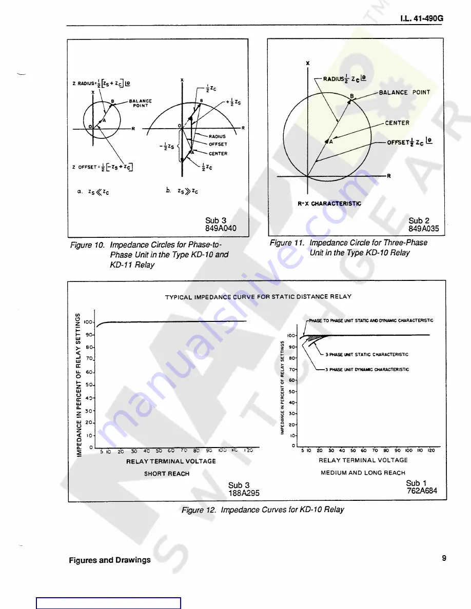
Страница 5: ...rate directional unit is required An inspection of Figure 10 indicates that the circle of the phase to phase unit is dependent on source im pedance ZS However the circle always goes through the line balance point impedance The reach at the compensator and line angle is con stant regardless of the system source impedance The broadening out of the characteristic circle with a relatively high source ...

Страница 6: ... will directionally operate for faults which produce 0 5 volts line to line and 2 7 ampere at the relay termi nals Sensitivity with 0 75 volts line to line for any tap is defined by Equation 8 8 The KD 10 relay may be set without regard to possi ble overreach due to dc transients 4 5 Distance Characteristic KD 11 3 Phase Unit The three phase unit of the KD 11 relay has a char acteristic circle whi...

Страница 7: ...R2A and R2C or P2A and P2C The maximum torque angle of the 3 phase unit of the medium 73 21 2 ohms and the long reach 1 27 36 6 ohms is set for 75 degrees at the factory and it may be set for any value from 60 to 78 degrees Other angles may set by changing resistor R3 The maximum torque angle of the 3 phase unit of the short reach 2 4 5 ohms relay is set for 60 degrees at the factory and may be se...

Страница 8: ...per unit value and is determined by the sum of the values between the L and the R leads The sign is positive when L is above R and acts to lower the Z set ting The sign is negative when R is above L and acts to raise the Z setting CAUTION The tap plate values of Tables I II and III are based on standard maximum torque angle settings In general recalibration of the relay to a torque angle other tha...

Страница 9: ...degrees 6 2 1 Guidelines to Achieve Optimum Application of the Relay to the Lines to be Protected a For Zone 1 application of KD 10 relays no setting or calibration correction should be made if the line angle is 65 degrees or higher for the medium and long range relays 50 degrees for the short range relay b For pilot trip or timed trip Zone 2 or 3 or KD 11 applications no setting or calibration co...

Страница 10: ...phase unit closest setting T 690 M 12 S 1 NOTE If for some reasons an exact correction is required to match up the line imped ance ZL at an angle α and the relay has been recalibrated from nominal maxi mum torque to a new maximum torque angle β α then the relay setting Z should be equal to 13 Example4 Relay with original θm 75 has been recalibrated to 60 and to be applied to 5 ohm line with line a...

Страница 11: ... leads identified as L and R for each transformer These leads come out of the tap plate each through a small hole one on each side of the vertical row of M tap inserts The lead connectors are held in place on the proper tap by connector screws Values for which an M setting can be made are from 18 to 18 in steps of 03 The value of a set ting is the sum of the numbers that are crossed when going fro...

Страница 12: ...ude of load or fault current relay settings relay impedance and other potential circuit burden con nected in parallel with the relay containing the com pensator To avoid any difficulties due to interaction between current and voltage circuits it is recommended that when PT fuses have been pulled to permit work on voltage circuits that these circuits should not be considered safe until the current ...

Страница 13: ...9 09 03 217 290 361 507 651 868 1 160 1 74 2 32 3 48 06 06 09 223 298 372 521 670 893 1 194 1 79 2 39 3 58 03 03 0 230 307 383 537 690 920 1 230 1 84 2 46 3 69 0 0 0 0 237 316 395 554 711 948 1 268 1 90 2 54 3 80 03 0 03 R OVER L 245 407 571 734 979 1 308 1 96 2 62 3 93 06 09 06 253 421 758 1 011 1 352 1 52 2 02 2 70 3 03 4 05 09 03 09 435 1 398 2 80 4 19 12 0 09 451 1 447 2 89 4 34 15 03 06 1 50 ...

Страница 14: ...9 3 63 5 18 7 25 10 4 15 5 12 09 0 798 1 06 1 33 1 86 2 66 3 72 5 32 7 45 10 6 16 0 09 09 03 821 1 09 1 37 1 91 2 74 3 83 5 47 7 66 10 9 16 4 06 06 09 845 1 13 1 41 1 97 2 82 3 94 5 63 7 88 11 3 16 9 03 03 0 870 1 16 1 45 2 03 2 90 4 06 5 80 8 12 11 6 17 4 0 0 0 0 897 1 20 1 49 2 09 2 99 4 19 5 98 8 37 12 0 17 9 03 0 03 R OVER L 926 1 54 2 16 3 09 4 32 6 17 8 64 12 3 18 5 06 09 06 956 1 59 2 23 3 ...

Страница 15: ...27 8 93 12 5 17 9 26 8 12 09 0 1 38 1 83 2 29 3 22 4 59 6 44 9 17 12 9 18 3 27 5 09 09 03 1 42 1 89 2 36 3 31 4 72 6 62 9 43 13 2 18 9 28 3 06 06 09 1 46 1 94 2 43 3 44 4 85 6 82 9 71 13 6 19 4 29 1 03 03 0 1 50 2 0 2 50 3 51 5 00 7 02 10 0 14 0 20 0 30 0 0 0 0 0 1 55 2 06 2 58 3 62 5 15 7 24 10 3 14 5 20 6 30 9 03 0 03 R OVER L 1 60 2 66 3 73 5 32 7 47 10 6 14 9 21 3 31 9 06 09 06 1 65 2 75 3 86 ...

Страница 16: ...neutral quantities The three phase unit maximum torque angle is always referenced to phase to neutral At any other angle α relay reach is 18 where Zθ relay reach at maximum torque angle θm Test current Iα is calculated as 19 Iθm test current at θm Equation 19 should be used to predict test current when plotting impedance circle response of the re lay The relay is set according to the following cha...

Страница 17: ...ned above when relay is set for other settings than specified here The test currents should be modified by following multi plier or 2 4 5 ohm range or 75 21 2 ohm range for 1 3 36 6 ohm range 11 6 Indicating Contactor Switch ICS Close the main relay contacts and pass sufficient dc through the trip circuit to close the contacts of the ICS The current should not be greater than the par ticular ICS t...

Страница 18: ... been taken apart for repairs or the ad justments disturbed Connect the relay for testing as shown in Figure 25 Figure 26 shows a four pole double throw switch in the test circuit that selects a phase to phase or a three phase fault voltage condition that will be ap plied to the relay voltage terminals The rotary switch switches the fault voltage to various terminals and thereby simulates any phas...

Страница 19: ...minals 7 and 8 Adjust core by turning it slightly until the contact arm floats or restrains very slightly b KD 10 ONLY Connect the relay terminals 7 and 8 together and apply rated ac voltage between 7 and 9 Adjust core until the contact arm just floats or restrains very slightly If this is not possible ro tate core 90 and adjust Recheck part 1 to de termine if contact is floating or restraining If...

Страница 20: ...ses maximum torque an gle and conversely decreasing the P3 value results in smaller angle For lower maximum torque angle adjustment below 70 degrees for medium and long ranges and for short range for settings below 55 degrees move red lead on fixed phase shifting resistor R3 to the oppo site terminal where R3 is adjustable resistor use it in combination with P3 setting without moving the lead 14 6...

Страница 21: ...PHASE UNIT TOP UNIT Relay Range 2 4 5 75 21 2 1 3 36 6 Trip Current 15 3 17 6 3 3 3 65 1 90 2 16 φ Phase shifter set at 90 105 105 The Nominal M T Angle 60 75 75 θm sin θ sin PHASE TO PHASE UNIT TAB AND TBC COMPENSATORS MAXIMUM SENSITIVITY ANGLE ADJUST MENT a Use 5 test connection for TAB compensator and 6 test connection for TBC compensator b Measure voltage across C2A for TAB and across C2C for ...

Страница 22: ...ompo nents of the phase to phase unit circuitry have been exchanged Tighten up the locking nut when fin ished If the unit does not operate within the speci Relay Range 2 4 5 75 21 2 1 3 36 6 Trip Current amperes 0 9 1 10 0 202 0 227 115 135 Phase shifter Set at current lagging 75 75 75 V A 1F VB 2F Vin V fault V A 1F VB 2F 120 2 2 59 fied limits then rotate the cylinder unit core 90 de grees and r...

Страница 23: ...tion 13 15 5 Indicating Contactor Switch ICS Close the main relay contacts and pass sufficient dc current through the trip circuit to close the contacts of the ICS The current should not be greater than the particular ICS tap setting being used for the 0 2 2 0 ampere ICS The operation indicator target should drop freely The contact gap should be approximately 0 047 for the 0 2 2 0 ampere unit betw...

Страница 24: ... S settings set 1 and M 15 check voltage drops starting at the minimum tap and each successive T tap Voltage readings will start at the millivolt level and increase with successive tap values Erratic voltage reading will indicate open tap These type of readings could be taken at any relay setting except when comparing any two relays or readings from the same relay at different times it should be c...

Страница 25: ...ATION To verify the proper current connections use the following procedure 3 CURRENT IDENTIFICATION If the verification check discloses incorrect cur rent connections the following procedure may be used to determine what is wrong However if one set of three switching combinations places the relay too close to the zero torque line use conventional techniques instead since identifica tion requires a...

Страница 26: ...EF could be flowing since the a2 lREF line is also intersects the solid part of the test 1b circle By the process of elimi nation for each set of 3 tests the actual cur rent is identified For example in Table V phase A receives lpn A whereas IPH A should be flowing In phase B IPH C is flow ing as shown in Figure 29 To extract this bit of information from Table V use the above table relating the ph...

Страница 27: ... 17 15 34 M t Closed C Open jump sw jaw to a 1 Closed Closed b Closed 4 H 3 j Closed A 9 Closed Open jump sw jaw to Closed 8L 3 j A a Closed Closed 2 H t B b 7 Closed M t Open jump sw jaw to Closed B a 3 Closed Closed b M t Closed C 8 Open jump sw jaw to 4 Closed 3 j A Closed Closed Closed 7 Open jump sw jaw to 5 M t B Closed Closed Closed 8 Open jump sw jaw to H t C Closed Closed Closed 6 9 t Blo...

Страница 28: ...C C O 4 O O C 2b C C C B 3a C C O 5 O O C 3b C C O C 1a C C o 6 o o o TABLE VI IDENTIFICATION EXAMPLE USING ASSUMED LOADING OF FIGURE 29 CURRENT POLARITY WHICH CAN PRODUCE OBSERVED CONTACT POSITION lREFPHASE RECEIVING CURRENT EXAMPLE OF CONTACT POSITION SWITCHING COMBINATION 32IREF REF alREF 1b o J A 2a O C 4 2b C JL B 3a O C 5 3b O t C o 1a O 6 t See Figure 30 for actual connections Appendix A 4 ...

Страница 29: ...change in characteristic in the same direc tion Evidence of drift should be traced to the particular element involved usually a ca pacitor or resistor and this element replaced a Perform all of the mechanical and electrical tests listed in the receiving acceptance sec tion of the applicable I L include the maxi mum torque angle test even if it is not called for in some I L s b Follow the appropria...

Страница 30: ...any convenient value if a phase shifter is used for direct angle reading 3 1 Calibration of the Relay for Maximum Torque Angle Experience has shown that calibration of the re lay for maximum torque angle is the procedure most susceptible to error Two potential sources of error are most common d Set the phase shifter for the desired maxi mum torque angle value Note the voltage a Instrumentation err...

Страница 31: ...0 130 volts to terminals 8 and 9 Vsg b Measure voltage across CSA c Set the current equal to Measure the voltage across the C3C capacitor with a high impedance voltmeter 5000 OHMS V1F2F volt 1 5 Relay Setting For 75 20 OHM reach KD 4 relays the mini mum voltage should be Vmin 3 5 x Vsg If Vmin less than 3 5 x VQQ replace capacitor C3C The current should be high enough to provide an accurate phase ...

Страница 32: ... further ad justment is required 3 4 Suggested Procedure for Replacement of C2C C2A Capacitors After the capacitors have been replaced b For 2 4 35 OHM reach KD 4 relays with sub A in the style number If the relay is cold decrease R3A setting 8 of total R3A R3F resistance a Open relay switch 9 phase C potential b Short terminals 7 and 9 on relay side and ap ply approximately 120 volts to terminals...

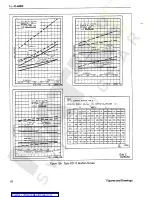
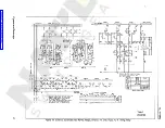
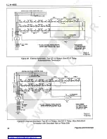
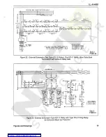
Страница 33: ...5 15 Typical Operating Time Curves for KD 11 Phase to Phase Unit 16 Typical Operating Time Curves of Type KD 11 Relay Three Phase Unit 75 20 Ohms 17a Type KD 10 Burden Curves 17b Type KD 10 Burden Curves 18a Type KD 11 Burden Curves 18b Type KD 11 Burden Curves 19 External Schematic Two KD 10 Relays One KD 11 and a Type KD 4 Timing Relay 20 External Schematic Two KD 10 Relays One KD 11 Relay Auto ...

Страница 34: ...I L 41 490G CO CO CO CB c o ct5 Q Q o ft Q CL S 25 S u Figures and Drawings 2 ...

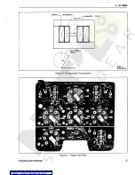
Страница 35: ...I L 41 490G PRIMARY CORE ADJUSTABLE ANGLE Sub 1 849A034 Figure 2 Compensator Construction Figure 3 Typical Tap Plate 3 Figures and Drawings Courtesy of NationalSwitchgear com ...

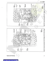
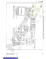
Страница 36: ...0 0 0 IA r OUTANCC UNIT UPPit UNIT far DISTANCE UNIT Orptn uHl T rHft hk JAt a All Mf TMNIfOlHO IICONOAIt oc Ain WP JRAlISfORHtft S E COMOA NY Uo 1 t I L _ 7 I s iK 1 c 0 ft cTi r l S H 1 3 r li i 1 Nl h I 1 01 M 30 J 11 I r r 0 o rf 01 1310 Wl Pcs cl I I m xy a Y S 02 HfO AUTO UANlfOBUI WO AUTO TAAHSFOWtft l 0 0 M 1 0 HANOI ICO KANDIC 160 0 A r T CT 0 T VQ r QTLOJ HIT WITCH TCST SWITCH I i 0 _ O ...

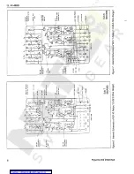
Страница 37: ...NIT DISTANCE UiltT UPPER U 1 IT 1 k I AIR UP TRANSFORMER SECONDARY I AIR CAP jKAilSTORHtR SECONDARY 60 JAB o s iTH i rli N ft 0 l s I _ 0 I 0 2 30 01 0 rr r o ICS Ktf 0 01 XQ ft OJ 20 0 Zltf 6 f I 3 02 MFD 2 0 0 AUTO milSFOJKEft AUTO TRANSPORTER Q RED HANOIE RED HANDLE 160 0 6 0 6 0 t o n 9 9 I TEST SWITCH TEST SWITCH I o o o o o 6 0 1 1 L 9 3 0 i TERMINAL I TERMINAL 2 4 l PM A PN 8 PIC M A PH B P...

Страница 38: ...C 3 C 00 Ml cc 3 A C 1 CA s i C T P 3 i 1 I f I 0 0 0 0 R c n 7 C 0 1 S I A H C E U N I I UPPER U N I T D l S T A N C E U N I T UPPER U N I T ifLI 11 p c P A 1 BC 4 JJAI M r i 1 A I R GAP TRANSFORMER SECONDARY A I R GAP TRANSFORMER SECONDARY s A i s J 0 6 06 U t L r i n 0 0 J e i 1 0 i rg 0 HJ 0 1 1 Krofu 1 nr f 0 2 MFD Zlffl AUTO TRAHSFORMIR AUTO TRANSFORMER 2 0 0 as a R E D HANDLE RED HANDLE 1 5...

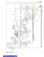
Страница 39: ...A Z X W Y V x K Ulk X Y B Y Ct I Z Z LA AC C L VCN lVZ JVCN VBN V VBN X VX CN IV V V V V lvZ Y Y Z Y D C B A NOTE THE VOLTAGE TRIANGLES AT EACH FAULT LOCATION A B CSD REPRESENT THE VOLTAGES SEEN BY THE KD IO RELAY TERMINAL LOCATED AT THE SHAOED BREAKER FOR 3 PHASE FAULTS OCCURING AT EACH LOCATION A B CBD r Sub 2 407 C 459 CO o O 4 Figure 8 Voltage and Current Conditions for the Three Phase Unit at...

Страница 40: ... yxY i z c h B Y _ _ A YZ 0 Z Ic v C ZC 10 Ic Zc ie ic zc IB IC ZC IB A B 0 fC NOTE THE VOLTAGE TRIANGLES AT EACH FAULT LOCATION A B CdD REPRESENT THE VOLTAGES SEEN BY THE KG IO RELAY TERMINAL LOCATED AT THE SHADED BREAKER FOR t TO 4 FAULTS AT EACH LOCATION A B cao Q c o f Q 3 a o i A Sub 3 408 C 161 3 IQ W Figure 9 Voltage and Current Conditions for the Phase to Phase Unit at the Shaded Breaker f...

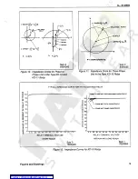
Страница 41: ...in z 90 80 3 PHASE UNIT STATIC CHARACTERISTIC 70 u 80 in j 70 UJ tr 3 PHASE UNIT DYNAMIC CHARACTERISTIC U 60 UJ o tr fc 60 w 50 40 z o 30 S 20 2 SO UJ o o CC 4D CC ui n_ 2 3 z UJ 20 CJ Q z 2 10 10 Q ui 0 Q _ 0 20 30 40 50 60 70 80 90 lO O i L i 2 0 5 10 20 30 40 50 60 70 80 90 100 HO 120 5 10 RELAY TERMINAL VOLTAGE RELAY TERMINAL VOLTAGE MEDIUM AND LONG REACH SHORT REACH Sub 1 762A684 Sub 3 188A29...

Страница 42: ...I L 41 490G Sub 1 185A346 Figure 13 impedance Circle for Three Phase Unit in Type KD 11 Relay Figures and Drawings 10 Courtesy of NationalSwitchgear com ...

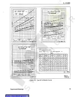
Страница 43: ...I L 41 490G Figure 14 Typical Operating Time Curves Normal Voltages Before Fault 120 Volts Phase to Phase Unit 11 Figures and Drawings Courtesy of NationalSwitchgear com ...

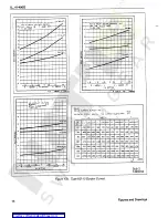
Страница 44: ...0 IT CURRENT TIME IMPEDANCE SETTING Sub 2 762A686 Figure 15 Typical Operating Time Curves forKD 11 Phase to PhaseUnit l M 0 MAX TORCUE ANGLE 75 CONTACT GAP 045 SIN 9 SIN 75 OPENING TIME IN CYCLES G TIME IN MILLtSECONDsT CLOSING TIME IN CYCLES 1 CLOSING TIME INMILLISECONDS 3 PHASE UNIT 9 I40 8 LOCATION OF FAULT IN OF RELAY SETTINGS 1 90 nn 75 50 io T1 120 7 100 6 20 Z 16 80 7 4 60 12 7 3 40 8 2 20 ...

Страница 45: ... 434 1 16 A 4 LkJ a PHJCC731 423 990 1 10 966 868 838 837 044 552 332 1 48 644 L 45 LkJ a 2 3 640 1 155 1 37 1 44 1 32 1 36 144 410 204 1 44 930 841 203 PHC 36 o PH BC34 I I 1 93 1 03 1 64 2 39 2 03 2 39 0 00 3 09 2 33 1 37 341 2 9 1 41 2 1 63 2 41 4 13 4 12 289 2 74 2 91 466 3 76 2 22 311 4 06 2 24 i 262 4 57 3 74 7 42 7 41 126 4 10 7 52 6 31 3 76 3 75 263 5 8 PHA I FB 148964 F27 15 18 03 0 v 03 ...

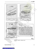
Страница 46: ...I L 41 490G 1426C54 Figure 17b Type KD 10 Burden Curves Figures and Drawings 14 Courtesy of NationalSwitchgear com ...

Страница 47: ...4 87 369 232 287 L2B 415 i 2l 537 mi 562 164 649 373 532 5 PHStSO PHCH3 1 16 487 338 350 I 4S 591 133 705 667 725 230 531 495 w 3 UJ tr PHC 11 UJ 1 45 S60 330 453 1 66 752 1 47 853 306 796 854 700 490 a 2 5 2 2 03 792 700 372 2 M 1 16 1 79 1 15 L25 U5 485 1 04 487 o PHA 14 2 90 24 U8 384 3 02 194 231 240 2 26 2 06 821 2 00 S7A I 4 06 201 196 418 4 46 321 3 09 259 133 2 22 3 68 358 891 5 80 3 4 5 3...

Страница 48: ...75 AMPS S 1 POTENTIAL CIRCUIT 69VL _N T Tfr OTH Tc Ta A TAP VARS WATT VARS WATT V A WATT VARS WATT V A V A VARS V A SET 965 409 771 573 516 664 616 1 05 249 416 411 065 1 5 5 1 31 998 765 942 576 1 40 478 642 906 260 2 0 577 020 Ss PH8 37 PHB 57 PHCM3 PHCM5 4 1 67 1 22 964 7 1 75 510 753 1 28 1 26 245 2 5 768 748 173 UJ s 2 40 1 68 1 32 2 17 2 51 733 2 03 2 20 383 UJ 3 51 1 16 112 282 1 3 z 3 56 2...

Страница 49: ...P COIL SUPERVISION LIGHT OR 0 2 AMP IC S UNIT IS USED ZONE 3 ZONE I ZONE 2 ra ITT C NE 21 1 TT TA 1 yv o IS TB Tfl 21 2 21 3 21 1 21 2 DEVICE Ui ZONE 2 z a ZONE 3 ZONE I z TA TA I I c 2M t I o o KD IO p r 21 2 2 KD IO I L i m i4 is re TB 21 2 t 213 14 l IS TB TB 213 21 3 3 Ko n 14 21 3 21 2 19 18 T t 301 21 3 21 2 21 1 21 f 2 TO 4 T1UIN6 18 Z T 19 16 19 52 PWR CKT BKR 21 3 2H TT 21 1 21 2 TC TS I ...

Страница 50: ...otransformer Termination STATION BUS PHASE ROTATION A B C A z B o c T o STD POTENTIAL CONN f ZONE 3 ui ZONE 2 ZONE 1 E A A t 21 3 21 1 21 2 o 2b 21 3 TA TA TA 21 19 T 18 19 T 18 19 T 2Q6 IB 21 1 a H c 21 1 21 2 TS TB II IT Tg TJ 15 T8 13 r 21 1 17 c IT i 21 2 21 3 21 3 21 1 U UI z z o o N N 21 2 21 3 21 3 21 1 21 2 II V ZONE 1 ZONE 3 ZONE 2 0 SIT68IA01603 y AUX CT 5 15 52 YY mTI OEVICE NUMBERS FOR...

Страница 51: ...O TERM S 13 4 12 15 4 14 17 4 16 19 4 18 OF KD 1 1 RELAY A 8 C LINE Sub 2 774B142 Figure 22 External Schematic Two Type KD 10 Relays One KD 11 Relay Wye Delta Bank Termination with Delta on Relay Side A TRIP QlRECTlON A STEP OP 1 TRANSf e GEN 52 c TRIP CIRCUIT 2i ii 21 13 iff Z T p r f 30 ii POS 7A 21 19 12 5 Zl301 T8 iZt30 i o 2i 2l 2 i TC 17 9 TZiMlJ Z1001 z t _2I T R A 2 03 9 09 L 06 i 4MA SA T...

Страница 52: ...NE 2 524 W r 52 o z 9 NEC a OEVICE CHART a DEV NO TYPE FUNCTION INT OiAG o ZONE 3 KQ tQ Zl PHASE ZONE 2 2 1 1 86 QA 988 ZONE I 2 1 1 1 6 17 x _ TS TT _ V Tfc X r 0 T y _ 21 3 o A n z T 3 KO 10 12 PHASE 880 A 988 2 1 2 21 3 23 PHASE KO ll 880 A 989 a 22 23 TIMER 2 TO 52 762 ASOO FOR 0 2 4 350 K 0 10 RELAY USE INT SCH 3490 A 8 I s fM 2 1 3 Te 2 1 21 3 21 2 21 2 21 1 21 I T txJ Z ION ALTERNATE CO T O...

Страница 53: ...2 F 7 3 F 9 3 F 7 3 F 8 rTEST CONNECTION TO CHECK 1 NO VARIACI REL OR ADJ I I J C 7 I I I I FOR 0 0 FAULT BRUSH IF SHOULD A L W A Y S B E A T H I G H E R i P O T E N T I A L T H A N 2 F W H E N R E F E R R E O T O P H 2 CONNECT FROM TO I I l _ l 5 IF 3 0 l 1 23 13 22 21 A E PHASE l _ _ i 2 3 0 A P 2 A A B 23 13 22 21 DOTTED CONNECTIONS FOR KD 11 RELAY ONLY FOR K D I O RELAY ONLY 2 F 4 i 3 0 F 2 C ...

Страница 54: ... ThE PHASE AN 6 LE NETER READING TO DETERMINE THE RELAY MAXIMUM TORQUE ANOU WHEN THE SELECTOR IS IN THE 3 0 POSITION I I I I I B C FAULT i L _ _ _ I I f 3 0 SELECTOR DOTTED CORRECTIONS FORUMl IELAT OILY FORFW REIAY OMIT 4 P O T SWITCH C A FAULT TO CHECK OR ADJUST TEST FAULT TEST W SELECTOR SWITCH CONNECT FROM TO NO VL C 3 0 22 21 22 21 Pa 23 13 A B 1 T f 2 A VT T 11 23 13 A B 2 O c Pit C A 13 17 4...

Страница 55: ...VE ORRCNT CURRENT FLOWING OUT SOLID LIKE CONTACT CLOSING TORQUE DRSH LIKE CONTACT OPENING TORQUE FOR 6pr ANGLES 3 FROM ZERO TORQUE THE PRODUCT OF I X T KtJST BE 17 I Lift CURRENT T T A P T SETTING THE THREE PHASE UNIT SHOULD RESPOND TO TESTS lb 2a AND 4 DISREGARD THREE PHASE LNIT ON ALL OTHER TESTS i POSITIVE DEGREES BASED ON CLPRENT LAGGING VOLTAGE POSITIVE ClRRENT CLRRENT FLOWING OUT Sub 4 185A0...

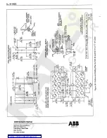
Страница 56: ... VIEW PANEL SPACERS FOR THIN PRNELS SCREW FOR THICK PANELS 7 USE 5 16 18 STUDS INTERNAL EXTERNRL i TOOTH WR 5 HER 5 f L J R il 2 IVJS 16 1 8 3 4 6 0 5 IG 2 0 5 0 8 NOTE I PROJECTION HARDWARE MUST BE ORDERED SEPARATELY 19 13 1 I U 1 0 8 594 15 09 563 DIR 1 4 2 9 25 4 2 688 6 8 2 8 190 32 SCREW 2 HOLES FOR THICK PANELS USE 190 32 STUDS n i 5 7 5 0 1 4 6 0 5 5 375 136 53 2 5 0 0 l 6 33 f 6 350 0 1 1 ...

Отзывы: