


I.L. 41-490H
22
2
if V
in
= 120 volts
V
fault
= 2 volts
volts. Now
trim up either voltage to get V
fault
= 2 volts.
The current required to close contacts of the top unit
should be:
With no current, relay contacts should stay open. If
relay contacts are closed recheck voltage settings,
incorrect voltage setting may result in negative se-
quence voltage phasing.
Set phase-shifter for maximum torque angle. Check
pickup current. It should be within the limits specified
above if not rotate core slightly until pickup current
falls within specified range. Connect relay for 2-3
(Test No. 6) and recheck pickup. It should be within
limits specified. For best trip calibration results ad-
just core so that trip current for Test No. 5 and No. 6
are equal.
Connect relay for Test No. 7. Check trip current. Use
XL
AC
adjustable reactor to bring relay response
within the specified limits. Moving red lead from front
terminal to rear terminal or from rear terminal to front
terminal of the reactor will reverse contact action of
the unit. Screwing in or out the adjustable core
should bring unit response within the limits. There
are three possible connections for reactor coils; se-
ries (loose coil termination leads connected togeth-
er), parallel (each loose lead connected to the fixed
terminals of the other coil), single front coil (omit
loose lead of the rear coil from the circuit, bury it in
insulation tubing). The reactor connections, should
not require any changes unless some of the compo-
nents of the phase-to-phase unit circuitry have been
exchanged. Tighten up the locking nut when fin-
ished. If the unit does not operate within the speci-
Relay Range
.2 - 4.5
.75 - 21.2
1.3 - 36.6
Trip Current
amperes
0.9 - 1.10 0.202 - 0.227 .115 - .135
Phase-shifter
Set at current
lagging
75˚
75˚
75˚
V
A
1
F
–
V
B
2
F
–
V
in
V
fault
–
=
=
V
A
1
F
–
V
B
2
F
–
120
2
–
2
-------------------
59
=
=
=
fied limits, then rotate the cylinder unit core 90 de-
grees and repeat test numbers 5, 6, and 7.
15.1 Maximum Torque Angle Check
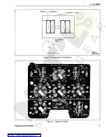
a. Use the No. 2 test switch position and lead con-
nections. This connection is for checking the max-
imum torque angle of the TAB compensator.
Set voltages and currents as per chart below.
Rotate the phase-shifter to find two angles
θ
1
and
θ
2
, at which the top unit contacts just close. The
maximum torque angle
θ
for the phase-to-phase
unit then is
degrees. Do not allow
more than
±
2 degrees error in this adjustment.
Tighten the locking nut.
∆
I
test
, for other than nominal maximum
torque angle, current should be:
(12)
Where
θ
m
= original maximum torque
β
= recalibrated maximum
torque angle
–————–—| Example 7 |———–———
For
θ
m
= I
test
= 10 amps
For new
β
= 60
˚
New
Increasing P
2A
or P
2C
value, rotation in clockwise
direction maximum torque angle, and conversely,
decreasing the P
2A
or P
2C
value results in smaller
angles.
For lower maximum torque angle than 70 degrees
move red lead on fixed phase-shifting resistor R
2A
and R
2C
to the opposite terminal. Where R
2A
and
R
2C
are adjustable, use it in combination with P
2A
and P
2C
without moving the lead.
Relay Range
0.2 - 4.5
.75 - 21.2
1.27 - 36.6
V
1F-2F = V2Fv3F
∆
I
test
(amp)
10
12
50
10.0
50
6.0
θ
1
θ
2
+
2
-------------------
30
–
I
θ
I
T
θ
m
sin
β
sin
----------------------
=
I
test
10
75
°
sin
×
60
°
sin
-------------------------------
11.1 amps
=
=