


I.L. 41-490H
19
nal 8 to each of the M and the M
A
taps. This voltage
should be equal to 100 (1 + the sum of values be-
tween R and the tap being measured). Example
100(1+.03+.09) = 112 volts.
Check the taps of M
C
in the same manner. Trans-
former that have an output different from nominal by
more than 1.0 volts probably have been damaged
and should be replaced.
13.4 Distance Unit Calibration
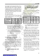
a. Make the following relay settings:
b. Read Section 11.1, Electrical Tests and Section
12.1, Distance Unit Electrical Test, to become fa-
miliar with testing connections, instrumentation,
and measurements. Use Figure 25 or 26 for test
connections.
14. Three-Phase Unit (Lower Unit) P
3
,
Core, & P
3A
Adjustments.
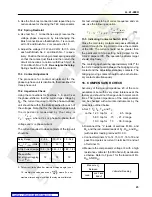
Use test connections #1 and set V
2F1F
= V
2F3F
= 25
volts. The current required for test should be:
For others angles set test current according to Equa-
tion (12).
14.1 P
3
Adjustment
To check the P
3
adjustment, measure voltage
across C
3A
. Vary phase angle in both directions of
the set value, to see that a low voltage across C
3A
(below 1 volt) is obtained at the maximum torque an-
gle setting. If minimum voltage is within 2 degrees,
do not readjust. If the minimum voltage is obtained
at some other angle readjust phase-shifting resistor
or potentiometer (P
3
) at the desired angle.
14.2 Core Adjustment
For an initial adjustment of the core, restraint spring
is to be set as above per Section 13.1, Initial Spring
Adjustment. The relay should be preheated for at
least one hour in the case with closed cover to com-
pensate for effects of self-heating.
a. Connect relay terminal 8 and 9 together, apply rat-
ed ac voltage between terminals 7 and 8. Adjust
core by turning it slightly until the contact arm
floats or restrains very slightly.
b. KD-10 ONLY: Connect the relay terminals 7 and
8 together and apply rated ac voltage between 7
and 9. Adjust core until the contact arm just floats
or restrains very slightly. If this is not possible, ro-
tate core 90
°
and adjust. Recheck part “1” to de-
termine if contact is floating or restraining. If not,
repeat parts 1 and 2.
14.3 P
3A
Adjustment
Remove current. Connect relay terminals 7 and 9 to-
gether and apply rated ac voltage between 7 and 8.
Adjust P3A so that the 3-ph unit contact just floats or
restrains very slightly. If P3A does not have sufficient
range to make this adjustment, use R3F resistor to
bring P3A within the necessary range.
This calibration point is temperature sensitive and
will change with time if capacitor C3C drifts. The re-
lay contacts must stay open when terminals 7 and 9
are shorted and rated voltage is applied between ter-
minals 7 and 8, with no current applied.
T h i s t e s t a s s u r e s p r o p e r r e s p o n s e o f t h e
3 - p h a s e - u n i t f o r 3 - p h a s e f a u l t s a n d f o r C A
phase-to-phase faults.
14.4 Final Core Adjustment for
KD-10 ONLY.
This check is done to prevent contact closing on cur-
rent-only.
a. Short circuit relay terminals 7, 8 and 9 together.
b. Pass 5 amperes in the current circuit in terminal
18 out terminal 19 increase the current to 30 am-
peres in convenient steps.
c. Relay contacts should stay open. If contacts
close, turn core further 90 degrees and repeat
parts 1, 2 and 3 of Section 14.2, Core Adjustment.
Relay Range
.2 - 4.5
.75 - 21.2
1.27 - 36.6
T, T
A
, T
B
, T
B
, T
C
M, M
A
, M
C
S, S
A
, S
C
1.23
+.15
1.0
5.8
+.15
1.0
10.0
+.15
1.0
Relay Range
.2 - 4.5 .75 - 21.2 1.3 - 36.6
Current
15.6
3.3
1.92
Phase-shifter Settings
60˚
75˚
75˚
The Nominal M-T-Angle
60˚
75˚
75˚