I.L. 41-490H
16
Make sure that correct lead-lag reference is estab-
lished. Once the phase-shifter is calibrated, remove
the wattmeter from the circuit. Make all phase angle
reading from phase-shifter scale. This method elimi-
nates the need for switching the current ranges in
phase angle meter when used and results in superi-
or accuracy. Always observe contact condition be-
fore current is applied. Closed contacts indicate re-
verse voltage sequence applied. Special attention
should be paid to the phase-to-phase fault mode.
Testing may be done outside the case for conve-
nience. All Current Readings include
±
6 percent
tolerance. This tolerance includes
±
2.5 percent fac-
tory tolerance and
±
3.5 percent allowance for total
instrumentation error.
All Phase Angle Settings are fault current lagging
the V
PH1-PH2
voltage.
The impedance measured by the 3-phase unit in test
1 (Figure 26) is
(14)
where V
L-L
is the phase-to-phase voltage and I
L
is
the test current; similarly, in tests 5, 6 & 7 of Figure
26 the phase-to-phase unit measures.
(15)
With phase-shifter set at maximum torque angle
(
θ
m
).
(16)
(17)
When testing the 3-phase unit, phase-shifter set-
tings are always set for 30
°
higher than nominal
maximum torque angle to account for test set-up
where all angle measurements are made with refer-
ence to phase-to-phase and not phase-to-neutral
quantities. The three phase unit maximum torque
angle is always referenced to phase-to-neutral.
At any other angle
α
, relay reach is
(18)
where Z
θ
= relay reach at maximum torque angle
θ
m.
Test current I
α
is calculated as
(19)
I
θ
m
= test current at
θ
m
Equation (19) should be used to predict test current
when plotting impedance circle response of the re-
lay.
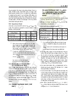
The relay is set according to the following chart.
If the relay is tested with other settings than specified
in acceptance test use voltage levels specified here,
except double the voltage specified for S = 2 settings
and triple for S = 3 settings.
When testing KD-11 relays with other settings than
specified here, refer to correction factors listed under
Section 4.5, Distance Characteristic: KD-11,
3-PHASE Unit.
Use Equations (16) and (17) to estimate test current,
and allow
±
5 percent tolerance as explained above.
11.2 Reverse Reach Check for KD-11
(.2 - 4.5 OHM Range Only)
Use voltage test connection #1 and set voltages
V
1F2F
= 50 volts V
2F3F
= 2 volts: connect current
lead “23” to “terminal 15, and current lead “22” to
lead marked “21”. Set phase-shifter for current to lag
V
1F2F
voltage by 30
°
this current connection is
equivalent to phase B current lagging V
BN
voltage
by 60
°
in the reverse directions. Adjust current for
ZR
V
L
L
–
1.73
I
L
-----------------
=
ZR
V
L
L
–
2
I
L
---------------
=
I
test
3 phase
(
)
V
L
L
–
1.73
Z
R
-------------------
=
I
test
Θ Θ
–
(
)
V
LL
2
Z
R
----------
=
Relay Range
.2-4.5
.75-21.2
1.3-36.5
T, T
A
, T
B
, T
B
, T
C
M, M
A
, M
C
S, S
A
, S
C
Z ohms
1.23
+.15
1.0
1.07
5.8
+.15
1.0
5.04
10.0
+.15
1.0
8.7
Z
Z
θ
θ
m
α
–
(
)
cos
=
I
α
I
θ
m
θ
m
α
–
(
)
cos
--------------------------------
=


