X1
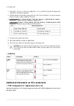
8 AO2
9 AGND
500 ohm
X1
8 AO2
9 AGND
1 kohm
1 kohm
0…
10
V
0…
10
V
■
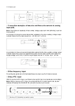
Connection examples of two-wire and three-wire sensors to analog
input (AI2)
Note:
The maximum capability of the auxiliary voltage output (24 V DC [250 mA]) must not
be exceeded.
An example of a two-wire sensor/transmitter supplied by the drive auxiliary voltage output
is shown below. Set the input signal to 4…20 mA, not 0…20 mA.
4…20 mA
+
-
P
I
...
AI2
AGND
+24V
DGND
An example of a three-wire sensor/transmitter supplied by the drive auxiliary voltage output
is shown below.The sensor is supplied through its current output and the drive feeds the
supply voltage (+24 V DC). Thus the output signal must be 4…20 mA, not 0…20 mA.
4…20 mA
+
-
P
I
...
AI2
AGND
+24V
DGND
OUT
■
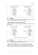
DI5 as frequency input
For setting the parameters for the digital frequency input, see the firmware manual.
■
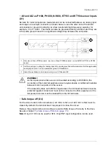
DI6 as PTC input
If DI6 is used as a PTC input, see firmware manual for how to set parameters accordingly.
Note:
If DI6 is used as a PTC input, the wiring and the PTC sensor need to be double
isolated. Otherwise the CMOD-02 I/O extension module must be used.
1
...
+24V
DI6
+
t
°
+
t
°
+
t
°
+
t
°
+
t
°
+
t
°
One to six PTC thermistors connected in series
1
112 Control unit
Содержание ACH580-04
Страница 1: ... ABB DRIVES FOR HVAC ACH580 04 drive modules Hardware manual ...
Страница 2: ......
Страница 4: ......
Страница 54: ...54 ...
Страница 88: ...88 ...
Страница 100: ...100 ...
Страница 118: ...118 ...
Страница 122: ...122 ...
Страница 124: ...124 ...
Страница 128: ...3 6 5 5 128 Maintenance ...
Страница 134: ...134 ...
Страница 156: ...R10 standard configuration 156 Dimension drawings ...
Страница 157: ...R10 with E208 0H354 H356 H370 0H371 Dimension drawings 157 ...
Страница 158: ...R10 with option B051 158 Dimension drawings ...
Страница 159: ...R10 with option E208 H356 P906 192 Tools R10 3 1 Dimension drawings 159 ...
Страница 160: ...R10 with option E208 0H371 H356 0H354 H370 P906 Tools 191 R10 2 1 160 Dimension drawings ...
Страница 161: ...R10 with option B051 P906 190 Tools R10 1 1 Dimension drawings 161 ...
Страница 162: ...R11 standard configuration 162 Dimension drawings ...
Страница 163: ...R11 with option E208 0H371 H356 0H354 H370 Dimension drawings 163 ...
Страница 164: ...R11 with option B051 164 Dimension drawings ...
Страница 165: ...R11 with option E208 H356 P906 Dimension drawings 165 ...
Страница 166: ...R11 with option E208 0H371 H356 0H354 H370 P906 166 Dimension drawings ...
Страница 167: ...R11 with option B051 P906 Dimension drawings 167 ...
Страница 186: ... Declaration of conformity 186 The Safe torque off function ...
Страница 206: ...Dimension drawing 206 External control unit option P906 ...
Страница 211: ...Dimension drawing The dimensions are in millimeters and inches CHDI 01 115 230 V digital input extension module 211 ...
Страница 212: ...212 ...
Страница 224: ...224 ...
Страница 226: ...226 ...
Страница 234: ...234 ...

