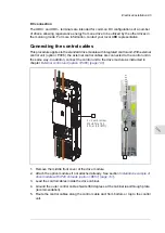
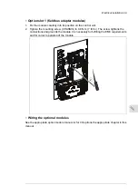


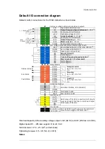
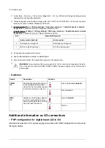
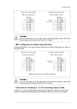
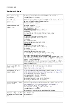


Default I/O connection diagram
Default control connections for the HVAC default are shown below.
Run status
Fault status
5)
4)
Damper actuator
max.
500 ohm
1…10 kohm
X1
1
SCR
Reference voltage and analog inputs and outputs
2
AI1
Signal cable shield (screen)
3
AGND
Output frequency/speed reference
: 0…10 V
1)
4
+10V
Analog input circuit common
5
AI2
Reference voltage 10 V DC
6
AGND
Actual feedback:
0…20 mA
1)
7
AO1
Analog input circuit common
8
AO2
Output frequency:
0…10 V
9
AGND
Motor current:
0…20 mA
X2 & X3
Analog output circuit common
10
+24V
Aux. voltage output and programmable digital inputs
11
DGND
Aux. voltage 24 V DC, max. 250 mA
2)
12
DCOM
Aux. voltage output common
13
DI1
Digital input common for all
14
DI2
15
Not configured
DI3
Stop (0) / Start (1)
16
DI4
Constant frequency/speed selection
3)
17
DI5
18
Not configured
DI6
Start interlock 1 (1 = allow start)
Not configured
19
RO1C
X6, X7, X8
Relay outputs
20
RO1A
21
RO1B
22
Damper control
250 V AC / 30 V DC
2 A
RO2C
23
RO2A
24
RO2B
25
Running
250 V AC / 30 V DC
2 A
RO3C
26
RO3A
27
X5
RO3B
Fault (-1)
250 V AC / 30 V DC
2 A
29
B+
Embedded fieldbus
30
A-
31
DGND
S4
Embedded fieldbus, EFB (EIA-485)
TERM
S5
BIAS
Termination switch
X4
34
Safe torque off
OUT1
Bias resistors switch
35
OUT2
36
SGND
37
IN1
38
IN2
X10
40
24 V AC/DC
24 V AC/DC+ in
Safe torque off. Factory connection. Both circuits
must be closed for the drive to start. See chapter
Safe torque off function.
41
24 V AC/DC- in
Ext. 24V AC/DC input to power up the control unit
when the main supply is disconnected.
4)
4)
6)
7)
Total load capacity of the Auxiliary voltage 24V (X2:10) is 6.0 W (250 mA / 24 V DC).
Digital inputs DI1…DI5 also support 10 to 24 V AC
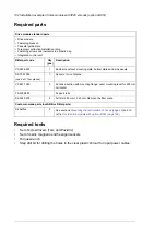
Terminal sizes: 0.14…2.5 mm
2
(all terminals)
Tightening torques: 0.5…0.6 N·m (0.4 lbf·ft)
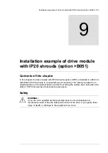
Notes:
Control unit 109
Содержание ACH580-04
Страница 1: ... ABB DRIVES FOR HVAC ACH580 04 drive modules Hardware manual ...
Страница 2: ......
Страница 4: ......
Страница 54: ...54 ...
Страница 88: ...88 ...
Страница 100: ...100 ...
Страница 118: ...118 ...
Страница 122: ...122 ...
Страница 124: ...124 ...
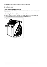
Страница 128: ...3 6 5 5 128 Maintenance ...
Страница 134: ...134 ...
Страница 156: ...R10 standard configuration 156 Dimension drawings ...
Страница 157: ...R10 with E208 0H354 H356 H370 0H371 Dimension drawings 157 ...
Страница 158: ...R10 with option B051 158 Dimension drawings ...
Страница 159: ...R10 with option E208 H356 P906 192 Tools R10 3 1 Dimension drawings 159 ...
Страница 160: ...R10 with option E208 0H371 H356 0H354 H370 P906 Tools 191 R10 2 1 160 Dimension drawings ...
Страница 161: ...R10 with option B051 P906 190 Tools R10 1 1 Dimension drawings 161 ...
Страница 162: ...R11 standard configuration 162 Dimension drawings ...
Страница 163: ...R11 with option E208 0H371 H356 0H354 H370 Dimension drawings 163 ...
Страница 164: ...R11 with option B051 164 Dimension drawings ...
Страница 165: ...R11 with option E208 H356 P906 Dimension drawings 165 ...
Страница 166: ...R11 with option E208 0H371 H356 0H354 H370 P906 166 Dimension drawings ...
Страница 167: ...R11 with option B051 P906 Dimension drawings 167 ...
Страница 186: ... Declaration of conformity 186 The Safe torque off function ...
Страница 206: ...Dimension drawing 206 External control unit option P906 ...
Страница 211: ...Dimension drawing The dimensions are in millimeters and inches CHDI 01 115 230 V digital input extension module 211 ...
Страница 212: ...212 ...
Страница 224: ...224 ...
Страница 226: ...226 ...
Страница 234: ...234 ...


