


6.
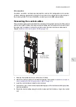
Ground the shields of the control cables at the clamp plate. The shields should be
continuous as close to the terminals of the control unit as possible. Only remove the
outer jacket of the cable at the cable clamp so that the clamp presses on the bare shield.
The shield (especially in case of multiple shields) can also be terminated with a lug and
fastened with a screw at the clamp plate. Leave the other end of the shield unconnected
or ground it indirectly via a few nanofarads high-frequency capacitor, eg, 3.3 nF / 630
V. The shield can also be grounded directly at both ends if they are in the same ground
line with no significant voltage drop between the end points.Tighten the screws to secure
the connection.
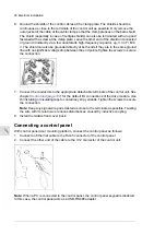
7.
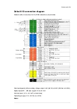
Connect the conductors to the appropriate detachable terminals of the control unit. See
chapter
for the default I/O connections of the drive module. Use
shrink tubing or insulating tape to contain any stray strands. Tighten the screws to secure
the connection.
Note:
Keep any signal wire pairs twisted as close to the terminals as possible. Twisting
the wire with its return wire reduces disturbances caused by inductive coupling.
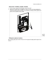
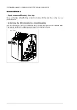
8.
Install the middle front cover back.
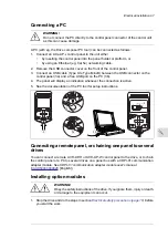
Connecting a control panel
With control panel door mounting platform, connect the control panel as follows:
1.
Connect an Ethernet cable to the RJ-45 connector of the control panel.
2.
Connect the other end of the cable to the X12 connector of the control unit.
Note:
When a PC is connected to the control panel, the control panel keypad is disabled.
In this case, the control panel acts as a USB-RS485 adapter.
96 Electrical installation
Содержание ACH580-04
Страница 1: ... ABB DRIVES FOR HVAC ACH580 04 drive modules Hardware manual ...
Страница 2: ......
Страница 4: ......
Страница 54: ...54 ...
Страница 88: ...88 ...
Страница 100: ...100 ...
Страница 118: ...118 ...
Страница 122: ...122 ...
Страница 124: ...124 ...
Страница 128: ...3 6 5 5 128 Maintenance ...
Страница 134: ...134 ...
Страница 156: ...R10 standard configuration 156 Dimension drawings ...
Страница 157: ...R10 with E208 0H354 H356 H370 0H371 Dimension drawings 157 ...
Страница 158: ...R10 with option B051 158 Dimension drawings ...
Страница 159: ...R10 with option E208 H356 P906 192 Tools R10 3 1 Dimension drawings 159 ...
Страница 160: ...R10 with option E208 0H371 H356 0H354 H370 P906 Tools 191 R10 2 1 160 Dimension drawings ...
Страница 161: ...R10 with option B051 P906 190 Tools R10 1 1 Dimension drawings 161 ...
Страница 162: ...R11 standard configuration 162 Dimension drawings ...
Страница 163: ...R11 with option E208 0H371 H356 0H354 H370 Dimension drawings 163 ...
Страница 164: ...R11 with option B051 164 Dimension drawings ...
Страница 165: ...R11 with option E208 H356 P906 Dimension drawings 165 ...
Страница 166: ...R11 with option E208 0H371 H356 0H354 H370 P906 166 Dimension drawings ...
Страница 167: ...R11 with option B051 P906 Dimension drawings 167 ...
Страница 186: ... Declaration of conformity 186 The Safe torque off function ...
Страница 206: ...Dimension drawing 206 External control unit option P906 ...
Страница 211: ...Dimension drawing The dimensions are in millimeters and inches CHDI 01 115 230 V digital input extension module 211 ...
Страница 212: ...212 ...
Страница 224: ...224 ...
Страница 226: ...226 ...
Страница 234: ...234 ...


