


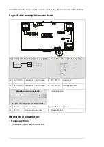


Start-up
■
Setting the parameters
1.
Power up the drive.
2.
If no warning is shown,
•
make sure that the value of both parameters
15.01 Extension module type
and
15.02 Detected extension module
is CMOD-01.
If warning A7AB
Extension I/O configuration failure
is shown,
•
make sure that the value of parameter
15.02
is CMOD-01.
•
set the parameter
15.01
value to CMOD-01.
You can now see the parameters of the extension module in parameter group
15 I/O
extension module
.
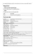
3.
Set the parameters of the extension module to applicable values.
Examples are given below.
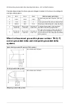
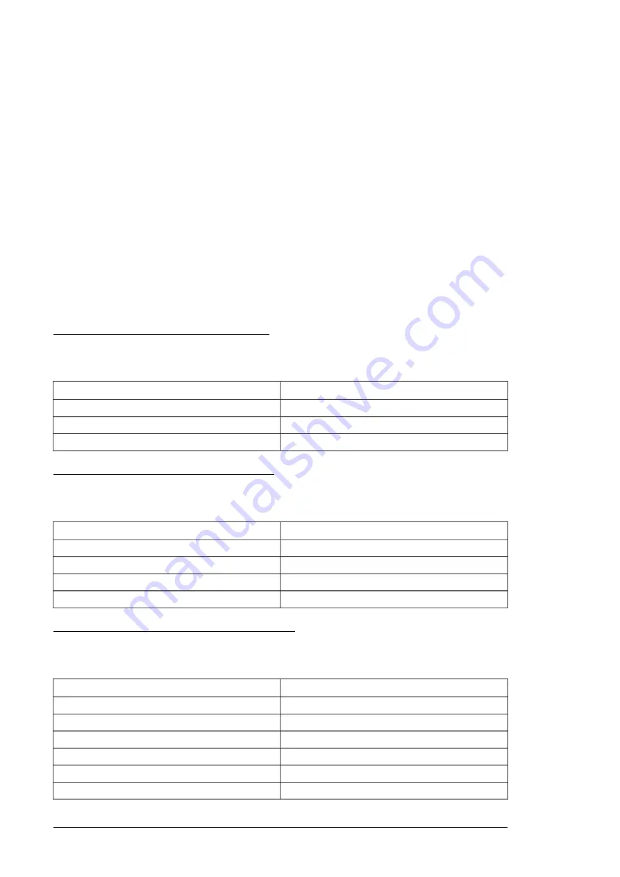
Parameter setting example for relay output
This example shows how make relay output RO4 of the extension module indicate the
reverse direction of rotation of the motor with a one-second delay.
Setting
Parameter
Reverse
15.07 RO4 source
1 s
15.08 RO4 ON delay
1 s
15.09 RO4 OFF delay
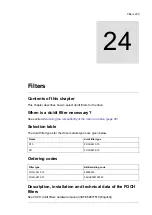
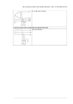
Parameter setting example for digital output
This example shows how to make digital output DO1 of the extension module indicate the
reverse direction of rotation of the motor with a one-second delay.
Setting
Parameter
Digital output
15.22 DO1 configuration
Reverse
15.23 DO1 source
1 s
15.24 DO1 ON delay
1 s
15.25 DO1 OFF delay
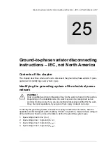
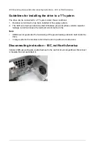
Parameter setting example for frequency output
This example shows how to make digital output DO1 of the extension module indicate the
motor speed 0... 1500 rpm with a frequency range of 0...10000 Hz.
Setting
Parameter
Frequency output
15.22 DO1 configuration
01.01 Motor speed used
15.33 Freq out 1 source
0
15.34 Freq out 1 src min
1500.00
15.35 Freq out 1 src max
1000 Hz
15.36 Freq out 1 at src min
10000 Hz
15.37 Freq out 1 at src max
216 CMOD-01 multifunction extension module (external 24 V AC/DC and digital I/O)
Содержание ACH580-04
Страница 1: ... ABB DRIVES FOR HVAC ACH580 04 drive modules Hardware manual ...
Страница 2: ......
Страница 4: ......
Страница 54: ...54 ...
Страница 88: ...88 ...
Страница 100: ...100 ...
Страница 118: ...118 ...
Страница 122: ...122 ...
Страница 124: ...124 ...
Страница 128: ...3 6 5 5 128 Maintenance ...
Страница 134: ...134 ...
Страница 156: ...R10 standard configuration 156 Dimension drawings ...
Страница 157: ...R10 with E208 0H354 H356 H370 0H371 Dimension drawings 157 ...
Страница 158: ...R10 with option B051 158 Dimension drawings ...
Страница 159: ...R10 with option E208 H356 P906 192 Tools R10 3 1 Dimension drawings 159 ...
Страница 160: ...R10 with option E208 0H371 H356 0H354 H370 P906 Tools 191 R10 2 1 160 Dimension drawings ...
Страница 161: ...R10 with option B051 P906 190 Tools R10 1 1 Dimension drawings 161 ...
Страница 162: ...R11 standard configuration 162 Dimension drawings ...
Страница 163: ...R11 with option E208 0H371 H356 0H354 H370 Dimension drawings 163 ...
Страница 164: ...R11 with option B051 164 Dimension drawings ...
Страница 165: ...R11 with option E208 H356 P906 Dimension drawings 165 ...
Страница 166: ...R11 with option E208 0H371 H356 0H354 H370 P906 166 Dimension drawings ...
Страница 167: ...R11 with option B051 P906 Dimension drawings 167 ...
Страница 186: ... Declaration of conformity 186 The Safe torque off function ...
Страница 206: ...Dimension drawing 206 External control unit option P906 ...
Страница 211: ...Dimension drawing The dimensions are in millimeters and inches CHDI 01 115 230 V digital input extension module 211 ...
Страница 212: ...212 ...
Страница 224: ...224 ...
Страница 226: ...226 ...
Страница 234: ...234 ...


