


79
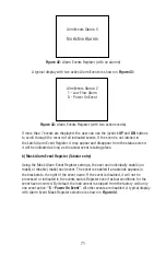
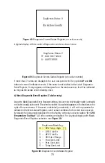
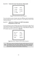
6.4.17.6 Solenoid Valve Parameters Diagnostic
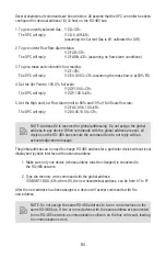
P:0.0030
1.3500
I:0.0000 B:0.1221
D:0.040 E:0.2499
V:1.00000 0
Figure 57:
Solenoid Valve Parameters Diagnostic
This menu selection provides information about valve
PID
and control loop parameters.
Consult your factory customer support representative for more details about Solenoid Valve
Parameters Diagnostic.
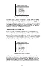
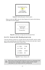
6.4.17.7 Reference Voltage and DSP Calculation
Diagnostic (read only)
This menu selection provides information about current 2.5Vdc reference voltage value as
well as different parameters of the Temperature/Pressure Compensation Algorithm, which
may be useful for controller troubleshooting (read only). A typical Reference Voltage and
DSP Calculation diagnostic screen is shown in
Figure 58:
REF: 3112 2.508
0.0001 14.7890
294.2611 300.151
VMCF: 0.985579
Figure 58:
Reference Voltage and DSP Calculation Diagnostic
NOTE: Actual content of the Reference Voltage and DSP Diagnostic screen may
vary depending on the model, device confi guration, and controller operational
state. Consult your factory customer support representative for more details
about Reference Voltage and DSP Calculation troubleshooting.
Содержание DPC
Страница 6: ...2...
Страница 120: ...116 APPENDIX I COMPONENT DIAGRAM Top Component Side...
Страница 121: ...117 Bottom Component Side...


