


10
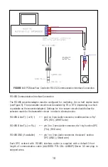
FIGURE 4:
DPC Mass Flow Controller RS-232 Communication Interface Connection
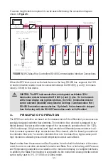
RS-485 Communication Interface Connection
The RS-485 converter/adapter must be confi gured for: multidrop, 2-wire, half duplex mode
(see Figure 5). The transmitter circuit must be enabled by TD or RTS (depending on which
is available on the converter/adapter). Settings for the receiver circuit should follow the
selection made for the transmitter circuit in order to eliminate echo.
RS-485 A line T(-) or R(-) ------ pin 2 on 3-pin Audio-connector, middle section or "tip"
DPC (RX-), (WHITE wire)
RS-485 B line T(+) or R(+) ------ pin 3 on 3-pins Audio-connector, the "ring" section DPC
(TX+), (RED wire)
RS-485 GND (if available) ------ pin 1 on 3-pin Audio-connector, the sleeve” section
DPC (GND), (Shield wire)
Each DPC ordered with RS-485 interface option is supplied with a default 3-foot
length of communication cable (AALBORG P/N: CBL- A485DP) Stereo 3.5 mm plug to
stripped wires.
Содержание DPC
Страница 6: ...2...
Страница 120: ...116 APPENDIX I COMPONENT DIAGRAM Top Component Side...
Страница 121: ...117 Bottom Component Side...


