


64
6.4.15.10 Signal Conditioner Settings
CAUTION: The signal conditioner parameters for your controller were set
at the factory to maintain the best performance. Do not change Signal
Conditioner parameters unless so instructed by your factory technical
support representative. Consult the factory for more information.
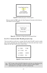
6.4.15.11 Program Set Point
The
Program Set Point
feature allows execution of custom, user-preset programs of up to
sixteen steps. During execution of the program, the user can activate or deactivate the
LOOP
mode and pause program execution. Various fl ow confi gurations may be preprogrammed:
ramping, pulsing, linearized increasing and/or decreasing of the fl ow. Before executing, the
program should be entered in the program table in the format: SETPOINT [% F.S.] - TIME
[sec.]. TIME means: time it takes for the value of the set point signal for the fl ow control-
ler, to linearly approach the SETPOINT value (ramping). Following settings are available for
“Program Set Point”
:
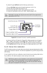
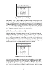
a) Program Set Point Mode (Tabular Entry)
This function determines whether the Program
Set Point
is
Enabled
or
Disabled
. The
following selections are available:
Enabled
or
Disabled.
The default entry is
Disabled
.
Program
Set Point
Mode selections can be set with the joystick
UP
and
DN
commands
and are accepted by pressing joystick
ENT
button.
b) Program Set Point Loop Mode (Tabular Entry)
This function determines whether the Program
Set Point
Loop
is
Enabled
or
Disabled
.
If
Loop
is enabled as the program reaches the last step it wraps around and again
starts execution from the fi rst enabled step. The following selections are available:
Enabled
or
Disabled
. The default entry is Disabled. Program
Set Point
Loop Mode
selections can be set with the joystick
UP
and
DN
buttons and are accepted by
pressing
joystick
ENT
button.
c) Program Set Point Step Mask (Tabular Entry)
Using
PSP
Steps Mask settings the user can enable (unmask) or disable (mask) any
step in the program. If the step is masked, the program will skip it and move to the
next enabled step. By default the unit is shipped from the factory with all program
5.2 Data Transmitted (TX activity) GREEN LED fl ashing momentarily
(about
200
ms
or
less).
6. Modbus Communication Interface Monitoring (optional):
6.1
Data Received (RX activity) RED LED fl ashing momentarily (about 200 ms or less).
6.2 Data Transmitted (TX activity) GREEN LED fl ashing momentarily
(about
200
ms
or
less).
Содержание DPC
Страница 6: ...2...
Страница 120: ...116 APPENDIX I COMPONENT DIAGRAM Top Component Side...
Страница 121: ...117 Bottom Component Side...


