


9
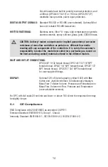
CAUTION: Before proceeding with communication interface connection, verify
the controller’s actual communication interface type. For devices with OLED
display, the interface type will be briefl y (for about 2 seconds) displayed on
the banner screen when power is applied. If your instrument does not have
a display, the communication interface type can be identifi ed by briefl y
pressing the multi-function button and monitoring status LED response
(see Section 6.5).
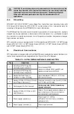
Communication Settings for RS-232/RS-485 communication interface The default baud
rate is 9600 baud (user-selected; see Section 5, Specifi cations).
Stop bit: ...............................
1
Data bits: ...............................
8
Parity: ...............................
None
Flow Control: ...............................
None
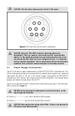
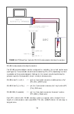
RS-232 Communication Interface Connection
Crossover connection must be established:
HOST PC RS-232 RX
Controller (RS-232 TX)
(pin 2 on the host PC DB9 connector) ------ pin 3 (Ring) of the 3-pin stereo jack connector (TX+)
HOST PC RS-232 TX
Controller (RS-232 RX)
(pin 3 on the host PC DB9 connector) ------ pin 2 (Tip) of the 3-pin stereo jack connector (RX-)
HOST PC RS-232 SIGNAL GND Controller (Digital GND)
(pin 5 on the host PC DB9 connector) ------ pin 1 (Sleeve) of the 3-pin stereo jack connector
Each DPC ordered with RS-232 interface option is supplied with default crossover 1.5- foot
long communication cable (AALBORG P/N: CBL-A232) DB9 female to stereo 3.5 mm Plug.
If custom length cable is required, it can be assembled using the connection diagram
shown in
Figure 4.
Содержание DPC
Страница 6: ...2...
Страница 120: ...116 APPENDIX I COMPONENT DIAGRAM Top Component Side...
Страница 121: ...117 Bottom Component Side...


