8
combustible materials must be provided in accordance with
information in this manual under LOCATION OF HEATER and
INSTALLATION OF VENT SYSTEM, and with the National Fuel
Gas Code and local codes.
PLANNING THE VENT SYSTEM
Plan the route of the vent system from the discharge of the blower
to the planned location of the vent terminal.
1. Layout the total vent system to use a minimum of vent pipe
and elbows.
2. This water heater is capable of venting the flue gases the
equivalent of twenty-five (25) feet of 2 inch pipe, sixty-five (65)
feet of 3 inch pipe, or one-hundred twenty-eight (128) feet of 4
inch pipe as listed in Table 1.
TABLE 1
Number of
2" Maximum
3" Maximum
4" Maximum
90° Elbows
Pipe (Feet)
Pipe (Feet)
Pipe (Feet)
1
20
60
120
2
15
55
112
3
10
50
104
4
--
45
96
5
--
40
88
6
--
35
80
The minimum vent lengths for each of the pipe sizes is one
90° on top of the unit plus 2' of straight pipe and the appropriate
termination.
NOTE:
The equivalent feet of pipe listed above are exclusive
of the termination. That is, the termination, with an installed
screen, is assumed to be in the system and the remainder of
the system must not exceed the lengths discussed above.
3. The blower discharge adapter is made to accept only straight
sections of 2" pipe. To start, a minimum of 2 inches of 2" pipe
must be attached to the blower discharge (See figure 5).
If using 2" inch vent pipe:
A minimum of 2 inches must be attached to the blower before
the first elbow. After the first elbow add the additional venting
required for the installation. The total system cannot exceed
the lengths discussed above, where each elbow is equal to 5
feet of straight pipe.
If using 3" or 4" inch vent pipe:
Two inches of pipe must be attached to the blower discharge
before adding a reducer to acquire the desired pipe diameter.
An appropriately sized 45 degree elbow (supplied locally – a
schedule 40 DWV) vent terminal must be obtained with an
equivalent screen (supplied in vent kit). The total system cannot
exceed the equivalent pipe lengths discussed above where
each elbow is equal to 5 feet of straight pipe (3" vent pipe) or
8 feet of straight pipe (4" vent pipe).
NOTE:
This unit can be vented using only PVC (Class 160,
ASTM D-2241; Schedule 40, ASTM D-1785; or Cellular
Core Schedule 40 DWV, ASTM F-891), Schedule 40 CPVC/
ASTM F-441), or ABS/ASTM D-2661) pipe. The fittings,
other than the TERMINATION should be equivalent to PVC-
DWV fittings meeting ASTM D-2665 (Use CPVC fittings,
ASTM F-438 for CPVC pipe and ABS fittings, ASTM D-
2661/3311 for ABS pipe. If CPVC or ABS pipe and fittings
are used, then the proper cement must be used for all
The drain line connected to this valve must not contain a reducing
coupling or other restriction and must terminate near a suitable
drain to prevent water damage during valve operation. The
discharge line shall be installed in a manner to allow complete
drainage of both the valve and line.
DO NOT THREAD, PLUG
OR CAP THE END OF THE DRAIN LINE.
VENT PIPE ASSEMBLY
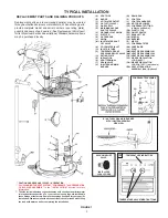
There are three parts of the vent pipe assembly that connect the
water heater exhaust (located on the lower back side of the water
heater) to the inlet of the blower assembly (mounted on top of the
water heater) as shown in Figure 1. These parts will need to be
assembled according to the instructions in the VENT PIPE
PREPARATION section of this manual. These PVC parts should
be assembled with ASTM D-2564 grade cement.
Assemble Vent Pipe Assemblies #1, #2 and #3 (See Figure 1)
prior to cementing. The preferred orientation of Vent Pipe
Assembly #1 (Condensate U-Assembly) is shown in Figure 4.
However this assembly may be rotated to a different orientation
as needed for the specific installation requirements. Note the
rotational orientation of each part by marking a line several inches
long across the joints. The long tube of Vent Pipe Assembly #2
should be approximately vertical. If it is found that either of the
two pieces of pipe in Vent Pipe Assembly #2 are too long for
proper fit-up, then remove as little material as possible to improve
the fit-up. Keep in mind that the pipes will insert slightly further
into the elbows when cement is applied as it acts as a lubricating
agent. The vertical distance from the bottom of the Condensate
U-Assembly to the floor that supports the water heater should be
approximately 0.25" (See Figure 4). Disassemble the parts and
cement back together using the alignment marks. After the cement
dries, attach the assembly to the blower and the water heater
exhaust using the supplied rubber boots and hose clamps.
A condensate trap is incorporated in the bottom of this vent pipe
assembly. See the CONDENSATE section of this manual for
further details.
VENTING
WARNING
NEVER OPERATE THE HEATER UNLESS IT IS VENTED TO
THE OUTDOORS AND HAS ADEQUATE AIR SUPPLY TO AVOID
RISKS OF IMPROPER OPERATION, FIRE, EXPLOSION OR
ASPHYXIATION.
VENT PIPE TERMINATION
The first step is to determine where the vent pipe will terminate.
See Figures 3, 8 and 9. The vent may terminate through a sidewall
as shown in Figure 8 or through the roof as shown in Figure 9.
IMPORTANT
The vent system must terminate so that proper clearances are
maintained as cited in local codes or the current edition of the
National Fuel Gas Code, ANSI Z223.1, 12.9.1 through 12.9.4.
Instructions on proper installation through a sidewall are provided
in Figure 3.
Plan the vent system layout so that proper clearances are
maintained from plumbing and wiring.
Vent pipes serving power vented appliances are classified by
building codes as "vent connectors". Required clearances from
Содержание BTX-80
Страница 24: ...24...


