5
Operation controls & Functions
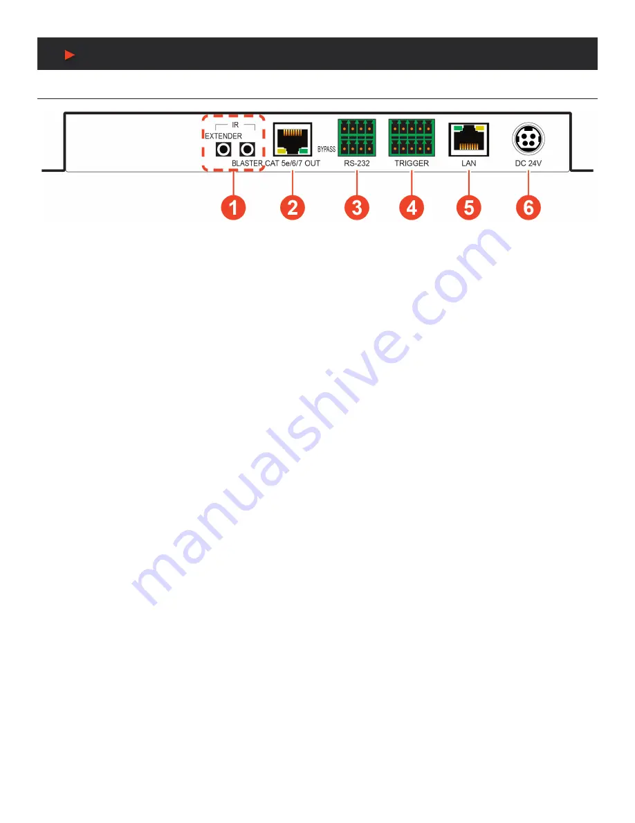
BACK Panel
q
IR EXTENDER PORT:
Connect to an IR Extender to receive IR control signals and extend them to devices connected to the other end
of the HDBaseT™ connection. Ensure that the remote being used is within direct line-of-sight of the IR Extender.
IR BLASTER PORT:
Connect to an IR Blaster to transmit IR signals from the other end of the HDBaseT™ connection to devices within
direct line-ofsight of the IR Blaster.
w
CAT5E/6/7 OUT PORT:
Connect to a compatible HDBaseT™ Receiver with a single CAT5e/6/7 cable for transmission of all data
signals. PoH will also be supplied to a connected compatible PD Receiver.
e
RS-232 4-PIN TERMINAL BLOCK (TOP):
Connect directly to a PC or laptop, or other serial control device with a 3 or 4-pin adapter
cable (as appropriate) to send RS-232 commands to control the unit. RS-232 BYPASS 4-pin Terminal Block (Bottom): Connect to a PC,
laptop, or serial controllable device with a 3-pin adapter cable for the extension of RS-232 signals between both ends of the HDBaseT™
connection.
r
TRIGGER 10-PIN TERMINAL BLOCK:
Connect to the Trigger Control Keypad (OPTIONAL) or any device with trigger switch
functionality to control assigned functions of the unit.
Note:
A minimum of 5V DC is required to activate a trigger.
t
LAN PORT:
Connect to a network switch or router for transmission and distribution of streamed video as well as to control the unit via
Telnet or WebGUI.
Note:
The maximum number of simultaneous stream connections is limited by available network bandwidth and the unit’s CPU load.
y
DC 24V PORT:
Plug the 24V DC power adapter into this port and connect it to an AC wall outlet for power.
A
NEU
VIDEO
Содержание ANI-28UHDDA
Страница 25: ...23 CONNECTION DIAGRAM A NEUVIDEO...
Страница 31: ...THIS PAGE IS INTENTIONALLY LEFT BLANK...


