


Managed Industrial Ethernet Switch User Manual
3onedata proprietary and confidential 45
Copyright © 3onedata Co., Ltd.
Instance
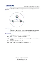
For example: creating coupling ring. Its basic architecture is shown as below:
Instance analysis
We can get the following picture by analyzing the coupling ring above.
There are three rings in coupling ring. Ring 1 and Ring 2 intersect Ring 3 respectively.
When setting ring in WEB interface, we can set Ring 1 and Ring 2 as single ring, Ring
3 as coupling ring. In coupling ring, we set the port in the link where the two rings
intersect as control port. The Port 2 of Device 105 in the picture above is the control
port. The analyses of each switch are displayed as follows:
105, 106, 107, 108 and 109 are in Ring 1; ring network ports are Port 1 and Port 2;
single ring; 105 is the master station, others are slave stations.
100, 101, 102, 103 and 104 are in Ring 2; ring network ports are Port 2 and Port 3;
single ring; 100 is the master station, others are slave stations.
100, 101, 105 and 106 are in Ring 3. It is a coupling ring. Port 1 is coupling port.
Port 2 is control port.
Operation Step 1: configuring Ring 1 in WEB interface
Configuring Device 105, 106, 107, 108 and 109 in the following steps respectively.


