background image


T


3D Printed project by ADDIMP 3D


Sea-Fury-1_12-LE-smooth-R 

L3 

50 

Symetrical 

Sea-Fury-1_12-W3L 

Sea-Fury-1_12-W3-LR 

R3 

Left aileron / Right 
aileron 

1+1 

17 

symetrical 

Sea-Fury-1_12-Aileron-L-
inter 

Sea-Fury-1_12-Aileron-L-
mid 

Sea-Fury-1_12-Aileron-L-
exter 

Sea-Fury-1_12-Aileron-LR 

Wing bellies (front & 
rear) 

1+1 

34 

Updated  V1.2


Sea-Fury-1_12-Wing-
belly_front 

Sea-Fury-1_12-Wing-
belly_rear 

Sea-Fury-1_12-Wing-bellies 

Servo mount & 
cover 

(1+1)x2 


symetrical 

1_12-servo_mount_L / R 

1_12-servo-cover_L / R 

1_12-servos-mounts_LR 


Tail 


Horizontal stabilizer 

1+1 

38 

Symetrical  

Sea-Fury-1_12-H-stab 

Sea-Fury-1_12-H_stab 

Elevator 

1+1 

Symetrical  

Sea-Fury-1_12-H_stab-L-flap 

Vertical stabilizer 

13 


Sea-Fury-1_12-V-Stab-fix 

Sea-Fury-1_12-V-stab-fix 

Vertical stabilizer 
with rudder 

20 


Sea-Fury-1_12-V-stab-wi-
rudder 

Sea-Fury-1_12-V-stab-wi-
rudder 

Rudder flap 


Sea-Fury-1_12-V-stab-
rudder-low 

Sea-Fury-1_12-V-stab-
rudder-up 


Accessories 


Motor mount for 
Pro-tronik DM2825 


Sea-Fury-1_12-MM-2825 

Sea-Fury-1_12-MM-2825 

Motor mount for 
Leopard 3536 


Sea-Fury-1_12-MM-3536 

Sea-Fury-1_12-MM-3536 

Motor mount for 
RacerStar 4108 


Sea-Fury-1_12-MM-4108 

Sea-Fury-1_12-MM-4108 

Содержание Hawker Sea-Fury FB 11

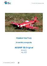
Страница 1: ...T 3D Printed project by ADDIMP 3D Hawker Sea Fury Assembly userguide ADDIMP 3D Original Release 2 May 2020 ...

Страница 2: ... 1947 It was the last propeller driven fighter to serve with the Royal Navy and one of the fastest production single engine aircraft ever built It was used during the Korean War in the early 1950s as well as against the 1961 Bay of Pigs Invasion of Cuba The Sea Fury was fitted with the Bristol Centaurus engine and armed with four wing mounted Hispano V cannons 20 mm Developed as an aerial fighter ...

Страница 3: ...nce like aerobatic aircraft Version history Version 2 New fuselage front area Better access to electronics and motor New wing Weight reduction and increase in the negative twist of the wing tip Version 1 2 1 Ailerons L R 3 parts instead 2 Release 1 2 W1L R Add supports on radiator duct factory gcode W2L R Port guns on a separate part W1L R F3 screw rear belly Enhance screw hole position W1L R Add ...

Страница 4: ...All the STL files factory files Simplify 3D and G codes this version can be made in 2 or 3 axis and the wing can be fixed either by screw or by rubber band The engine mount is installed using M3 screws self locking nut instead of self tapping screws 4 Balance Center of gravity 67 to 72 mm Recess for balance ...

Страница 5: ...A A profile for Simplify 3D is proposed as example in the directory factory MK3PLA 3DP fff Setup 3S PLA std o Engine Pro tronick DM 2825 950 kV o Engine Roxxy C3542 810 kV o ESC Pro tronik 40 45 A o Battery LiPo 3S 1800 to 2200 mA 45C 6S o Racerstar 4106 600 kV o Emax 3515 650 kV o propeller 9x6 or 9x7 o ESC 40 45 A o Battery LiPo 6S 1800 mA Check the connectors between ESC and battery 3 or 4 serv...

Страница 6: ...ww rcjetshobby com en 81 controleurs 6 Print settings the use of the LW PLA from Colorfab is explain in a specific file in the factory directory Few quantity of parts needs special parameters they are describe when needed G Codes are based on Prusa Mk3 Mk 3S Ø1 75mm PLA The use with other 3D printer or filament will have different results Even in the same brand of filament color may change results...

Страница 7: ... moves 0 4mm Possible wipe option activated may replace a part of retraction The 3 or 4 fist layers should be at 2 outline perimeter shells The same for the 3 or 4 last select outside shell first Temperatures Bed 55 to 60 C Extruder 215 to 230 C No cooling 7 Sea Fury parts diagram Part Qtty Weigt h g Comment STL file Factory file G code Fuselage F1 1 79 Sea Fury 1_12 F1 Sea Fury 1_12 F1 ...

Страница 8: ...Front Sea Fury 1_12 Bat Hatch Sea Fury 1_12 Bat Hatch LN Front coverLN 1 To be used with F1 long nose Sea Fury 1_12 bat hatch Front LN Rear cover 1 Sea Fury 1_12 Bat cover_Rear Lock 1 1_12 Bat cover_lock Lock housing 1 Sea Fury 1_12 Bat cover_housing Wing L1 1 73 Left right are not symetricals Sea Fury 1_12 W1L Sea Fury 1_12 W1L gcode with or without supports R1 1 68 Sea Fury 1_12 W1R Sea Fury 1_1...

Страница 9: ...2 servo cover_L R 1_12 servos mounts_LR Tail Horizontal stabilizer 1 1 38 Symetrical Sea Fury 1_12 H stab Sea Fury 1_12 H_stab Elevator 1 1 Symetrical Sea Fury 1_12 H_stab L flap Vertical stabilizer 1 13 Sea Fury 1_12 V Stab fix Sea Fury 1_12 V stab fix Vertical stabilizer with rudder 1 20 Sea Fury 1_12 V stab wi rudder Sea Fury 1_12 V stab wi rudder Rudder flap 1 Sea Fury 1_12 V stab rudder low S...

Страница 10: ... option Wing support 1 1 Symetrical Sea Fury 1_12 L Main gear Wing support Sea Fury 1_12 landing gear V2 Splint 6 Sea Fury 1_12 LR Main gear splint Main gear leg 2 Sea Fury 1_12 LR Main gear leg Main gear door 1 1 Symetrical Sea Fury 1_12 L Main door Tailwheel R leg 1 1 symetrical Sea Fury 1_12 R tailwheel leg Tailwheel support 1 Sea Fury 1_12 tailwheel support Main wheel hub 4 Sea Fury 1_12 LR Ma...

Страница 11: ...beginning by root section L1 with L2 then L3 Same order for the right wing Assemble the three parts of the aileron int mid ext There are two hinges by aileron They must be cut in a 20 x 25 mm rectangle then adjusted in place then assemble aileron with hinges and with wing before assemble the full wing Be careful not to twist the wingtip during the entire bonding process You can use Ø2 rods to join...

Страница 12: ...te parts to facilitate the printing It could be cannons or smooth Both parts are identified Left L and Right R Parts should be glued on respectively W2R and W2L 8 2 Servo mount To facilitate the mount and setup of the servo it is used a special mount with cover There is a mount for 16g servos and an other for 8g servos W4L W3L W2L W1L ...

Страница 13: ... one have a letter to indicate the side L for the left wing R for right wing You can use a servo to keep it straight Then fit the servo on the bay adjust the linkage to the aileron easily once finish screw the cover to the mount with 2 screws 2 x 10 Left wing installation ...

Страница 14: ...T 3D Printed project by ADDIMP 3D 8 3 Wing bellies They are glued together then glued on the wing Working with the wing under the fuselage is better to help center ...

Страница 15: ... part it will be cut later F4 glue with F3 cut the lower opening under F3 beware of the wing fixture F5 select the 2 or 3 axis part open the elevator control area glue with F4 F1 choose normal length or elongated version help to balance with lightweight motor setup install battery strap install the M3 self locking nuts glue with F2 Final install wire pushrod for elevator and rudder glue the H stab...

Страница 16: ...T 3D Printed project by ADDIMP 3D F1 normal or long nose F2 F3 F4 F5 2 axis F6 2 axis only ...

Страница 17: ...T 3D Printed project by ADDIMP 3D F5 3 axis H Stabilizer Fixed rudder V stab with rudder ...

Страница 18: ...he trade If you wish to use another engine do not hesitate to ask us for a special support specifying the dimensions of your engine Install 2 of the M3 nuts in the housings in F1 the last is on the motor mount Use a needle nose pliers to facilitate the placement of the nuts A point of CA glue allows to fix the nut in place Also install the strap for the battery The openings come out of print Cut a...

Страница 19: ...vel of the F4 centering ribs 9 3 Fuselage assembly F1 to F6 First check all the parts remove all the residual skirt to sand if needed the parts Check that all sections of the tube for the elevator and rudder pushrods are well cleared and fully open along the entire length Assemble all the parts without any glue to check the well adjustment and alignement ...

Страница 20: ...or filament Check the diameter of the different holes receiving these rods If necessary re drill until Ø2 All other sections are centered with ribs Place the toothpick or the pin in a hole then cut at 2 mm height At this time you can install the battery strap before assembly F1 with F2 F1 F2 pins locations ...

Страница 21: ...sections A peripheral rib helps with centering check the absence of plots or wires linked to the print do not bond F6 part to the fuselage until horizontal stabilizer is mount You can glue each part from F1 to F5 together Use CA with activator if needed ...

Страница 22: ...d F1 to F4 at least it is necessary to open the underside of F2 F3 to give access for electronics You can use cutter electrical driller or hot cutter Paie a special attention to the internal wing support which is very close to the cutout 9 5 Battery hatch Area to open lock Lock housing Front cover Rear cover ...

Страница 23: ...nt rear part you can use Ø2 mm rod tohelp centering Put the lock in the rear part see below This lock use a clip instead a spring Then glue the lock housing under the rear cover Take care to not glue the lock Large access to the battery and the motor ...

Страница 24: ...if needed for assembly First glue the horizontal stabilizer to the fuselage Check the correct angularity between these 2 elements Once done glue the hinges if using film cut as per the cut out below and adjust on parts Prepare the Ø1 mm elevator pushrod wire use a Z bend pliers at one extremity only ...

Страница 25: ...nted project by ADDIMP 3D Put the pushrod wire on the fuselage Z bended extremity at the elevator side Cut the plastic on the area below Install the elevator on the pushrod then glue the elevators to the hinges ...

Страница 26: ...T 3D Printed project by ADDIMP 3D Finish with gluing F7 and the vertical stabilizer ...

Страница 27: ...f the axle must be 128 mm 1 Once the whole H stab assembly is glued on the fuselage glue the fin Check perpendicularity Carry out the length of the rudder pushrod in the same way as for the elevator Connect the horn of the rudder flap to the pushrod then present the assembly on the fuselage push the pin completely into the rudder flap Secure with a drop of cyano the axis in the lower part of the r...

Страница 28: ...T 3D Printed project by ADDIMP 3D 11 Wing fixture 11 1 With rubber band Use 120mm rubber band attach around the printed rod With wing ...

Страница 29: ...ew and nut Use M6 nylon screw and nut If use screw and nut you may have to adapt le nut s housing First adjust the housing for the nut then glue it with CA bond 12 Receiver ans ESC Both can be installed on a specific housing in F2 Nut in the housing ...

Страница 30: ... For aileron and elevator use 8 mm displacement 25 to 30 exponential For the first flights you can start with more exponential and or reduced displacement Do not forget that the manual launch involves a low speed for the first meters of flight ...

Страница 31: ... 14 Landing gear optional Left landing gear Support Ø3 mm piano wire Splints screws Ø3x10 Main gear leg Main wheel hub Main wheel tyre Main gear door Assembled Exploded view Installation Left wing shown Right wing symetrical 3 mm 9 mm ...

Страница 32: ...T 3D Printed project by ADDIMP 3D Tailwheel installation The use of the tool to bend the piano wire 1 Install Ø6 mm hard wood or metal pin in the holes and a Ø4 mm screw in the lower hole ...

Страница 33: ...T 3D Printed project by ADDIMP 3D 2 Put the wire along the screw tight it 3 Bend the wire along the path on the tool 4 cut the wire at the correct length with the tool ...

Страница 34: ...T 3D Printed project by ADDIMP 3D Cut here ...

Страница 35: ...eld to support the plane fully assembled Part Quantity File Front 1 Sea Fury 1_12_Stand Front stl Rear 1 Sea Fury 1_12_Stand Rear stl Side short 2 Sea Fury 1_12_Stand Side front stl Side long 2 Sea Fury 1_12_Stand Side rear stl Splint 2 Sea Fury 1_12_Stand Splint stl Front Rear Side short Side long Side long Side short Splints ...

Страница 36: ...rint yourself on the file deco pdf There are many web site which propose photos of the Sea Fury Below some ideas F AZXJ https www airliners net search keywords F AZXJ G CBEL https www airliners net search keywords G CBEL G FURY https www airliners net search registrationActual G FURY NX15S https www airliners net search keywords NX15S NX232MB https www airliners net search keywords NX232MB NX878M ...

Страница 37: ...y Flying at high speed and practicing high G maneuvers puts the airframe of the aircraft under great stress which can lead to breakage in flight o Be vigilant and careful when you practice this type of flight no express or implied warranties do not engage ADDIMP 3D or its partners o Respect your local reglementation for flying Please use these files only for your own purpose Do not send it further...

Отзывы: