50
C
HAPTER
4: I
NSTALLING
AND
C
ONFIGURING
THE
N
ET
W
ARE
D
RIVER
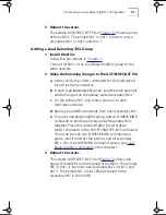
3 Enter the slot number.
The slot number is the PCI slot number of the physical NIC.
The following fields appear:
■
Node Address
■
Log Message Level
When multiple NICs are installed, you must determine
which physical NIC corresponds to which PCI slot to
correctly connect the cables to the hub or the switch.
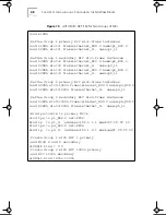
4 Press F3 to set the frame types.
Use the arrow keys to select frame types. Select as many
of the supported frame types as required. Adding frame
types after exiting the installation program is best done by
editing the AUTOEXEC.NCF file. The default is 802.2 only.
Ethernet_802.3, Ethernet_II, and Ethernet_SNAP frame
types are also supported.
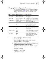
5 To use the default MAC address of the NIC, leave
the Node Address field blank.
The default MAC address is recommended for most
installations.
6 Select
Log Message Level
and press Enter.
7 Select which messages to log from the pop-up box
and press Enter.
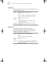
All messages are printed to the system console screen and
to the SYS:\SYSTEM\SYS$LOG.ERR file. All messages are
logged by default.
8 When you have set all the configuration values,
select
Save parameters and load driver
.
The installation program loads the configured driver and then
writes the appropriate LOAD and BIND commands to the
AUTOEXEC.NCF file. The system assigns a network number.
9 Enter a network number, or press Enter to select the
system-assigned number.
If no errors are encountered, the installation asks whether
you want to select an additional network driver.
Book Page 50 Monday, June 7, 1999 2:14 PM
Содержание EtherLink 3C985B-SX
Страница 1: ......
Страница 9: ......
Страница 15: ......
Страница 26: ...Creating a Load Balancing RSL and VLAN Configuration 25 Figure 4 Creating a Load Balancing RSL Group ...
Страница 29: ...28 CHAPTER 3 INSTALLING AND CONFIGURING THE WINDOWS NT DRIVER Figure 6 Creating a VLAN ...
Страница 91: ......
Страница 107: ......
Страница 113: ......


