178
C
HAPTER
5: C
ONFIGURING
P
ATH
B
UILDER
S600 M
ODULES
, P
ORTS
,
AND
A
PPLICATIONS
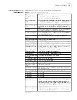
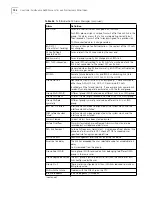
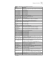
Onhook Detection
—Enables or disables on-hook detection. When you enable
on-hook detection, bandwidth is automatically reallocated based on detection of
an on-hook condition, as specified by the signalling type.
Signalling Type
—The signalling application type:
No
Signalling
,
E&M/PLAR
,
FXO-LoopStart
,
FXS-LoopStart
, or
FXO-GroundStart
for CBR DSX;
R2
for CBR E1.
You can only modify this field in structured voice mode. In this mode, you can
select any signalling application type except
No
Signalling
. If you try to set the
Signalling
Type
to
No
Signalling
in structured voice mode, you will get an error. In
structured/unstructured data modes, the
Signalling
Type
defaults to
No
Signalling
and cannot be modified. Configured under
Manage Card
. Select
E&M/PLAR
to
configure for dynamic bandwidth allocation (DBA) over ISDN PRI.
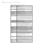
DS0 Channels
—The associated DSOs which have been assigned to the specified
ATM VC connection. All available DSO channels are automatically allocated in
unstructured mode. In structured mode, the DSO channels are bit-coded, with
each bit representing one DSO channel. You can assign DSO channels in
structured mode only. Channel conflicts within a T1/E1 port interface will result in
an error.
QSIM/HSIM/FAM Card Virtual Circuit Configuration Parameters
The parameters that appear on the QSIM, HSIM, or FAM Add Virtual Circuit screen
vary, depending on the configuration of the serial port that is being connected:
Frame Relay, DXI, or HDLC/SDLC.
The configuration of the card you select on the List Card menu sets the attribute
selection for the virtual circuit configuration parameters. If you configure a virtual
circuit and then change serial port attributes—from DXI to Frame Relay or vice
versa—the circuit will be deleted.
Frame Relay Virtual Circuit Parameters
If the serial port is configured as a
Frame Relay port, you must set the following virtual circuit parameters:
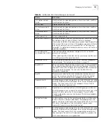
Interworking Mode
—The Frame Relay/ATM interworking mode:
Network
or
Service
.
Start Frame Relay DLCI—
The starting Frame Relay data link connection
identifier:
16...991
. DLCI is used to identify a Frame Relay local connection. In
Network interworking mode, contiguous values of DLCIs can be mapped to a VCI.
Many DLCI to One VCI mapping is supported as well as One DLCI to One VCI
mapping.
End Frame Relay DLCI—
The ending Frame Relay data link connection identifier:
16...991
. DLCI is used to identify a Frame Relay local connection. In Network
interworking mode, contiguous values of DLCIs can be mapped to a VCI.
Encapsulation Mode—
The encapsulation data goes around the data packet and
is used to identify the packet; select
1 (Transparent)
or
2 (Translation)
. This feature
is offered only for Service interworking mode.
Transparent
—Used for point-to-point frame relay interconnection. See
Figure 138. Frame Relay Forum 8 (FRF.8) Service Interworking for this is being
implemented. There are two modes at which FRF.8 specifies a mode which is
transparent and is in fact 1490 over ATM.
Содержание 3C63100-AC-C - PathBuilder S600...
Страница 8: ...INDEX 3COM CORPORATION LIMITED WARRANTY ...
Страница 14: ...xiv CHAPTER SUPPLEMENTARY REGULATORY INFORMATION ...
Страница 18: ...18 ABOUT THIS GUIDE ...
Страница 28: ...28 CHAPTER 1 SYSTEM DESCRIPTION ...
Страница 74: ...74 CHAPTER 3 GETTING STARTED ...
Страница 230: ...230 INDEX ...


