Predator ULTRA Installation Manual V2.1.25.3
Page 17
© 360 Vision Technology Ltd.
K.Craik
15-08-2016
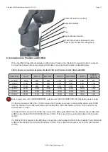
Predator washer image
Water Jet direction (vertical)
Adjustable Nozzle
Tie
Tube
Nozzle Bracket located
Fit M8 Plain Washer Between Nozzle
Bracket and Predator Mounting Base.
6 Connections to Predators with HMA
When the HMA (Hinged Mount Adaptor) is fitted to the Predator, the ‘Predator Composite Cable’ is not used.
Connections between the power supply and Predator use conventional cables as detailed below.
30Vdc Power connections between Predator PSU and Predator that is fitted with HMA
Cable Size
No IR
SIR110
SIR140WL
SIR160
SIR250SWL
SIR275
SIR400/
SIR550S
0.75mm²
85m
32m
32m
30m
30m
30m
5m
1.00mm²
113m
43m
43m
40m
40m
40m
10m
1.50mm²
170m
65m
65m
60m
60m
60m
15m
2.50mm²
283m
108m
108m
100m
100m
100m
25m
3.00mm²
340m
130m
130m
120m
120m
120m
30m
4.00mm²
450m
173m
173m
160m
160m
160m
40m
Note: Large Lamp units (SIR400/SIR550S) must be used with the PRED-PSU-SM (30vdc 6A) power supply.
If a thermal camera is fitted (50 - 100mm lens) in the Predator use a coax to connect the video signal CON8
from the Predator that is fitted with HMA and Predator PSU (PCB-000-0240-xx) CON2. This is used for the
thermal camera video.
If an Alarm PCB is present in the PSU then connect the data signal CON8 from the Predator that is fitted with
a HMA to the Predator PSU (PCB-000-0240-xx) CON2. This is used for the serial alarm data to the Predator
ULTRA.
If a Washer PCB is present in the PSU then connect the control signal CON8 from the Predator that is fitted with
a HMA to the Predator PSU (PCB-000-0240-xx) CON9. This is used for the washer control from the Predator
ULTRA.
!


