ZAMAN RÖLELERİ
MCB-15 Zaman Rölesi
TIME RELAYS
MCB-15 Time Relay
MCB-15 zaman rölesi 24-240 VAC/DC geniş besleme aralığı, 0.1
saniyeden 100 saate kadar ayarlanabilen zaman skalası ve 4 farklı
zaman fonksiyonu ile endüstriyel ve yerel uygulamalarda kullanılır.
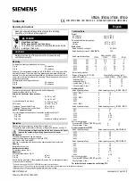
① Zaman Çarpanı Ayarı:
Seçilen zaman diliminin çarpılacağı zaman
çarpanıdır. Cihaz üzerinde bulunan ayar trimpotu ile 0.1’den 1’e kadar
ayarlanır.
②Zaman Dilimi Ayarı:
Seçilen zaman bölgesinin maksimum değerini
gösterir. Ayarlanmak istenen çalışma süresine göre 8 farklı zaman
diliminden seçim yapılır.
Çalışma süresi = Zaman dilimi x Zaman çarpanı
Örnek:
Çalışma süresi 3 dakika olarak ayarlanmak isteniyorsa,
T = 10 x 0.3
T = 3 dakika
③Fonksiyon Ayarı:
Cihazın çalıştığı zaman fonksiyonu gösterir.
A Çekmede Gecikmeli:
Besleme gerilimi uygulandığında ayarlanan t
bekleme süresi saymaya başlar. t süresinin bitmesinin ardından röle
çıkışı ON konumuna geçer. Cihazın besleme gerilimi kesilene kadar
röle çekili konumda kalır. t süresi bitmeden besleme gerilimi kesilirse,
sayılmış zaman silinir ve besleme gerilimi tekrar uygulandığında t
süresi tekrar saymaya başlar.
B Kontrol Girişli Bırakmada Gecikmeli:
Besleme gerilimi ve tetikleme
sinyali uygulandığında röle çeker. Tetikleme sinyali kesildiğinde t
süresi saymaya başlar ve süre sonunda röle bırakır. t süresi bitmeden
tekrar sinyal uygulandığında sayılan süre silinir ve tetikleme sinyalinin
kesilmesiyle birlikte yeniden saymaya başlar.
C Bırakmada Gecikmeli:
Besleme gerilimi uygulandığında röle çeker
ve ayarlanan t süresi saymaya başlar. t süresi sonunda röle çıkışı
OFF konumuna geçer. Cihazın besleme gerilimi kesilene kadar röle
konumunu korur. t süresi bitmeden besleme gerilimi kesilirse sayılmış
zaman silinir ve besleme gerilimi tekrar uygulandığında t süresi tekrar
saymaya başlar.
D Simetrik Flaşör:
Besleme gerilimi uygulandığında ayarlanan t süresi
saymaya başlar. t süresi sonundan röle çeker ve ayarlanan t süresi
tekrar saymaya başlar. Süre sonunda röle bırakır. Besleme gerilimi
kesilene kadar bu döngü devam eder.
Zaman diyagramları için sayfa 4 ‘e bakınız.
MCB-15 time relay uses in industrial and domestic applications with
24-240 VAC/DC wide operating range, adjustable time range from 0.1
seconds to 100 hours and 4 different timing functions.
① Time Multiplier Adjustment:
It is the time multiplier that the
selected time range is multiplied. It is set from 0.1 to 1 with the
adjustment trimpot on the device.
②Time Range Adjustment:
It shows the maximum value of the
selected time range. One of 8 different time range is selected
according to the operation time to be set.
Operation time = Time range x Time multiplier
Example:
If it is wanted to be set operation time to 3 minutes
T = 10 x 0.3
T = 3 min
③Function Adjustment:
It shows the function of the device.
A ON Delay:
When the supply voltage is applied, the adjusted time t
is started to count. After the adjusted t has expired, the output relay
switches into ON position. This status remains until the supply voltage
is interrupted. If the supply voltage is interrupted before the expiry of
the adjusted time, the time already expired is erased and is restarted
when the supply voltage is applied again.
B OFF Delay with Control Input:
When the supply voltage and
the triggering signal are applied, the output relay switches into ON
position. When the triggering signal is interrupted, the time t is started
to count and the output relay switches into OFF position at the end of
the time. If the triggering signal is applied again before the time t has
expired, the time already expired is erased. The time restarts again
when the triggering signal is interrupted.
C OFF Delay:
When the supply voltage is applied, the output relay
switches into ON position and the adjusted time t is started to count.
The output relay switches into OFF position at the end of the time t.
This status remains until the supply voltage is interrupted. If the supply
voltage is interrupted before the expiry of the adjusted time, the time
already expired is erased and is restarted when the supply voltage is
applied again.
D Symmetric Flasher:
When the supply voltage is applied, the
adjusted time t is started to count. The output relay switches into ON
position at the end of the time t and the adjusted time counts again.
The output relay switches into OFF position at the end of the time t.
This cycle countinues till the supply voltage is interrupted.
A8246/Rev.2
A8246/Rev.2
④Besleme ışığı:
Besleme gerilimi uygulandığında cihaz üzerindeki
ON LED’i yanar. Besleme gerilimi kesildiğinde ON LED’i söner.
⑤Röle ışığı:
Röle çekili konumdayken cihaz üzerindeki OUT LED’i
yanar. Röle kontağını bıraktığında OUT LED’i söner.
Teknik Bilgi
Işletme Gerilimi (Un)
: 24 – 240 VAC/DC
İşletme Frekansı
: 50/60 Hz
Çıkış Kontağı
: 1 CO, 8 A, 2000 VA (cosϕ=1)
Zaman Aralığı
: 0.1 sn – 100 saat
Ortam Sıcaklığı
: -5 °C / + 50 °C
Koruma Sınıfı
: IP20
Boyutlar
: Tip PK 22
Bağlantı Şekli
: Pano içine dikey veya klemens rayına
Ağırlık
: 60 gr
Boyutlar Bağlantı Şeması
Güvenli Kullanım ve Kurulum İçin Uyarılar
Aşağıdaki talimatlara uyulmaması halinde yaralanma ve ölümle
sonuçlanabilecek durumlar ortaya çıkabilir.
•
Cihaz üzerindeki herhangi bir işlemden önce tüm besleme
gerilimlerini kesiniz.
•
Cihaz şebekeye bağlı iken ön paneli çıkarmayınız.
•
Cihazı solvent veya benzeri maddelerle temizlemeyiniz. Cihazı
temizlemek için sadece kuru bez kullanınız.
•
Cihazı çalıştırmadan önce bağlantılarının doğru olduğunu
kontrol ediniz.
•
Cihazınızdaki herhangi bir sorunda yetkili satıcınızla temas kurunuz.
•
Cihazı panoya monte ediniz.
Yukarıdaki önlemlerin uygulanmaması sonucu doğabilecek
istenmeyen durumlardan üretici firma hiç bir şekilde sorumlu
tutulamaz.
Not:
Kontak dayanımı omik yükte (ör = Akkor flemanlı ampul, Rezistanslı
cihazlar) 8A’dir. Endüktif (ör = AC motor, florasan (Sargılı balastılı), vb..)
ya da Kapasitif (ör = Led Sürücüler, UPS, florasan(Elektronik Balastlı),
vb..) yük anahtarlanacaksa kontaktör kullanılması tavsiye edilir. Aksi
taktirde cihazın röle kontaklarında yapışma meydana gelebilir.
Bu ürün, 30.05.2008 tarih ve 26891 sayılı resmi gazetede yayınlanan
EEE Yönetmeliğinin Madde 2 ve Ek-1A madde 9 kapsamındadır.
Please, see the page 4 for time diagrams.
④Supply LED:
When the supply voltage is applied, ON LED on the
device illuminates. When the supply voltage is interrupted, ON LED
extinguishes.
⑤Relay LED:
When the output relay is ON position, OUT LED on the
device illuminates. When the output relay is OFF position, OUT LED
extinguishes.
Technical Data
Rated Voltage (Un)
: 24 – 240 VAC/DC
Rated Frequency
: 50/60 Hz
Output Contacts
: 1 CO, 8 A, 2000 VA (cosϕ=1)
Delay Time
: 0.1 sec – 100 hours
Ambient Temperature : -5 °C / + 50 °C
Protection Class
: IP20
Dimensions
: Type PK 22
Installation
: Surface mounting or on the mounting rails
Weight
: 60 gr
Dimensions
Connection Diagram
Precautions for Installation and Safe Use
Failure to follow those instructions will result in death or serious injury.
•
Disconnect all power before working on equipment.
•
When the device is connected to the network, do not remove the
front panel.
•
Do not clean the device with solvent or the like. Only clean the
device with a dried cloth.
•
Verify correct terminal connection when wiring.
•
Electrical equipment should be serviced only by your competent
seller.
•
Mount device to panel.
No responsibility is assured by the manufacturer or any its
subsidiaries for any consequences arising out the use of this
material.
Note:
The contact resistance at ohmic load (e.g.: Incandescent bulb,
Resistance devices) is 8A. It is recommended to use a contactor if the
inductive load (e.g.: AC motor, fluorescent, etc.) or capacitive load
(e.g. : Led Drivers, UPS, Fluorescent(Electronic Ballast), etc.) switch.
Otherwise adhesion may occur in relay contacts.
A
B
C
D
-15
A
B
C
D
-15
① Zaman çarpanı
ayarı
① Time Multiplier
Adjustment
② Zaman dilimi
ayarı
② Time Range
Adjustment
③ Fonksiyon ayarı
③ Function
Adjustment
④Besleme ışığı
④ Supply LED
⑤Röle ışığı
⑤ Relay LED
A1
B1
24-240
VAC/DC
A2
27,5
45,6
58
48
A1
B1
24-240
VAC/DC
A2
27,5
45,6
58
48