9
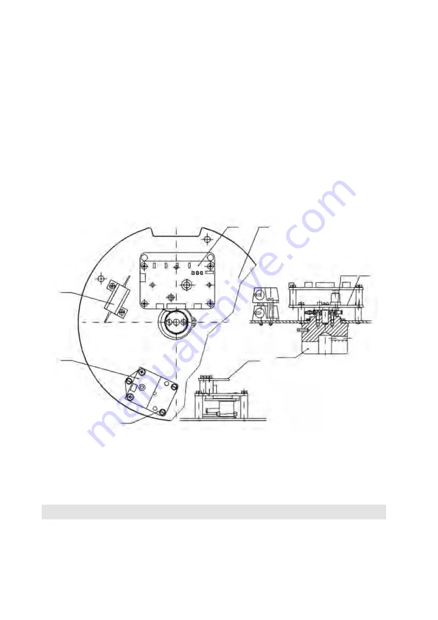
Fig. 2 -
Basic plate
11
15
1
14
13
14
2,18
4,12
8
c) Control box (Fig. 1)
With the actuator in its usual position
(axis of the output shaft in horizontal plane),
the box is installed on the
actuator side – opposite to the lever. The position gearbox 15
(Fig. 2)
is installed in the box on the motherboard of
the control part
(Fig. 2, 2a).
The modules are mutually and with the terminal board box interconnected with cables
(see the figure).
The control box is covered with the lid 6
(Fig. 1).
To facilitate assembling, the output shaft is realized as sectional. The output end of the shaft is attached directly to
the control board and this assembly is then pushed into the output shaft cavity.
d) Lever assembly (Fig. 1)
The lever assembly consists of lever 40 mounted on the output shaft of the power gear unit and circular flange 8 fitted
on its face with a T-groove in which stops 15 are adjustably mounted to limit the lever movement. The flange and
the stops are fixedly connected to the cast-iron box of the power gear unit.
e) Terminal board box 5 (Fig. 1)
It is connected with the control box by a flange and serves for fitting other parts, control circuits, and terminals
for inlet conductors. The terminal board box can accommodate local control and, in case of the version DMS2,
also a display.
Bushings or the connector are screwed in the terminal board box 5
(Fig. 1).
The terminal board and other components
(for instance, connector for service connection of a computer)
in the
terminal board box are easily accessible after removing the cover of the terminal board box. Cable bushings are used
for tight passing of the cables into the terminal board box.
Other version of the terminal board box is fitted with a connector for connecting supply voltage and control signals.
The connector counterpart with two bushings is included in the delivery.
8. ELECTRONIC OUTFIT
Electro-mechanical control board is replaced with the electronic system
DMS2 or DMS2 ED. Both systems
scan position of the output shaft and torque of the electric actuator by contact-free magnetic sensors. Long
service life is guaranteed for the contact-free sensors that do not get mechanically worn.
The sensor of the output shaft position is absolute and does not require any backup power supply
in case supply voltage is disconnected during operation of the electric actuator. Both systems can be set


