48
9. UNPACKING AND STORING
Packaging of the actuators is carried out to suit the transport conditions and the distance of the place of designation.
When unpacking the actuator, check that no damage to the equipment was caused during transport and compare the
data on the actuator rating plates with those contained in the order and accompanying documentation. Any discrepancy,
defect or damage should be immediately reported to the supplier. When the actuator is not immediately installed it should
be stored in a clean room with a temperature within the range of - 25 °C to + 50 °C and relative humidity up to 85 % where
there are no aggressive vapours. It is only before the actuator is installed that excessive slush should be removed. If the
actuator is to be stored or shut down for a longer period it is advisable to place a bag with the drying agent in the control
chamber and the terminal box.
(the agent is not available from the actuator manufacturer).
10. CHECKING OF EQUIPMENT CONDITION
Prior to installation, check that the actuator was not damaged during storing. Make a visual check to be sure that
the individual parts and particularly the control and terminal boxes have not corroded.
11. ACTUATOR LOCATION
The actuators can operate in any position provided that the axis of the electric motor remains horizontal.
The actuators can be used even in a position with the electric motor upwards. However, in this case, the gear box
should be topped up with oil.
The actuator should be located so that easy access is obtained to the handwheel and the terminal box.
The actuators should be located so that there is no risk of injury to persons and/or damage to the property during
installation, operation, adjustment, maintenance or dismantling. If this is not possible the organisation making
the project or installing the technological equipment integrated with the actuator should take such precautions that
the risk of injury to persons and damage to the property is completely avoided.
Warning:
When shipped to customers, the actuator packets contain bags with silica gel or other suitable siccative in
order to protect the actuators against air humidity during transportation. Before putting the actuator into operation,
the control box and the terminal board box should be checked whether the silica gel bags have been removed; if not,
they should be removed from the actuator and disposed of ecologically.
12. INSTALLATION
The actuators should be mounted through tapped holes 49 in their bearing feet by means of screws
(Fig.1).
The bearing surfaces on which the actuators are mounted, should be levelled out so that no deformation of the box can
be caused by retightening. In their basic design variant, the actuators are supplied complete with a lever and stops.
In this design variant, they are suitable for their main application, i.e., control of turning flaps, louvers and valve levers.
When the actuator used is fitted with a lever and stops the lever of the actuator should be coupled to that of the
controlling device by means of a pull rod.
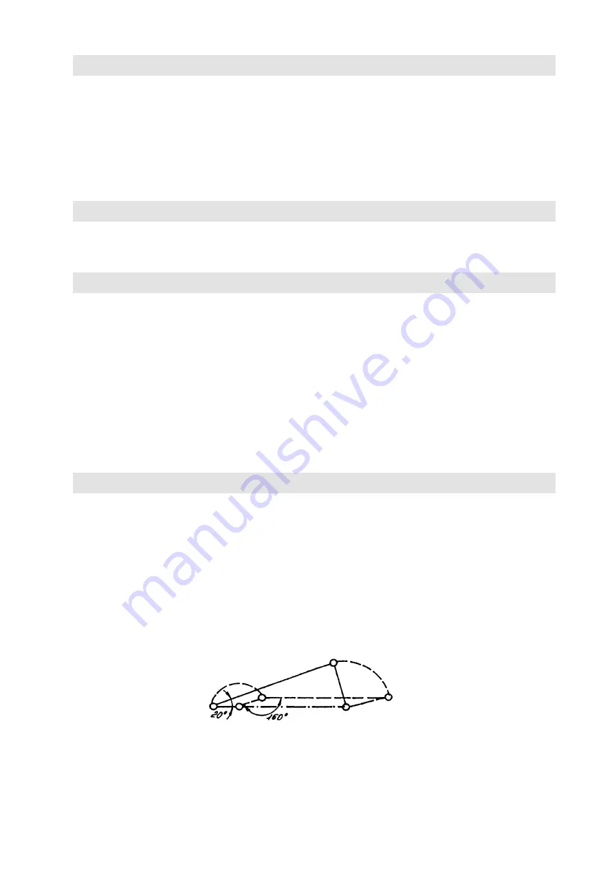
During mounting, care should be taken to ensure that, in either extreme position, the angle between the pull rod and
the actuator lever is not less than 20°, but not more than 160° since otherwise there is the danger of an uncontrolled
increase in the acting forces and thus the risk of damage to the actuator and/or reduction of its service life. A similar
principle should be also applied on the side of the controlled device
(Fig. 3).
The arrangement of the mechanism
(length
of the actuator lever, pull-rod length, lever arm length of the fitting)
should be selected so that the actuator can be
brought into either extreme position of the regulating unit according to the local conditions and the general directions.
Nevertheless, the actuators can be supplied without lever and stops. In this case, they can be used for direct
flanged connection to a flap, a ball valve, etc. When the torque-limit switching facility is to be used the controlled device
should be fitted with stops.
When wiring the actuators, the corresponding standards and other regulations should be observed.
Fig. 3 –
Acturator Lever hub with a rod


