background image

9650-0807-01 Rev. C

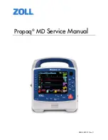
Propaq MD Service Manual

1

Preface

Overview

The ZOLL

®

 Propaq

®

 MD Service Manual is intended for the trained biomedical technician 

whose responsibility is to identify malfunctions and/or make repairs at the subassembly level. 
The Propaq MD Service Manual has five main sections and two appendixes.

Preface—

Contains safety warnings and an overview of the manual’s contents. Be sure to 

review this section thoroughly before attempting to use or service the Propaq MD unit.

Chapter 1—Maintenance Tests

 describes step-by-step procedures for various maintenance 

tests.

Chapter 2—Troubleshooting

 provides a listing of error messages to help the service 

technician detect faults and repair them.

Chapter 3—Disassembly Procedures 

describes step-by-step procedures for disassembling 

modules in the Propaq MD unit.

Chapter 4—Replacement Parts List 

displays a complete list of ZOLL part numbers for field 

replaceable parts available for the Propaq MD unit, allowing the service person to identify and 
order replacement parts from ZOLL.

Chapter 5—Functional Description

 provides technical descriptions for the Propaq MD major 

subassembly modules.

Appendix A—

Propaq MD Electrical Hardware Interconnect Diagram and Propaq MD Signal 

and Power Interconnect Schematic.

Appendix B—

Contains simulators and settings that may be used to assess the performance of 

the NIBP module.

Summary of Contents for Propaq MD

Page 1: ...Propaq MD Service Manual 9650 0807 01 Rev C...

Page 2: ...015 ZOLL Medical Corporation All rights reserved Rectilinear Biphasic SurePower and ZOLL are trademarks or registered trademarks of ZOLL Medical Corporation in the United States and or other countries...

Page 3: ...MD Options Maintenance Tests 7 MAINTENANCE TESTS 8 Physical Inspection of the Unit 8 Operational Tests 9 Leads Test 15 Heart Rate Display Test 16 Heart Rate Alarm Test 17 Power Supply Test 19 Leakage...

Page 4: ...MOVING THE HANDLE 61 REMOVING THE PRINTER MODULE 62 DISASSEMBLING THE MAIN UNIT 64 REMOVING THE FRONT ENCLOSURE MODULE 68 REMOVING THE DISPLAY MODULE 70 REMOVING THE ETCO2 AND NIBP MODULES 74 REMOVING...

Page 5: ...VERVIEW 125 PROPAQ MD ELECTRICAL HARDWARE INTERCONNECT DIAGRAM 126 PROPAQ MD SIGNAL AND POWER INTERCONNECT SCHEMATIC 127 Appendix B OVERVIEW 129 NIBP Simulator Performance 129 Fluke Biomedical BP Pump...

Page 6: ...TABLE OF CONTENTS iv www zoll com 9650 0807 01 Rev C...

Page 7: ...r 2 Troubleshooting provides a listing of error messages to help the service technician detect faults and repair them Chapter 3 Disassembly Procedures describes step by step procedures for disassembli...

Page 8: ...ucts when used in conjunction with pacing defibrillation electrodes and adapter units from other sources If unit failure is attributable to pacing defibrillation electrodes or adapter units not manufa...

Page 9: ...800 348 9011 in North America Technical Service If the ZOLL Propaq MD unit requires service contact the ZOLL Technical Service Department Telephone 1 978 421 9655 1 800 348 9011 Fax 1 978 421 0010 Em...

Page 10: ...ice Center To locate an authorized service center contact the International Sales Department at ZOLL Medical at the above address Tamper Proof Labels ZOLL products must be repaired by qualified indivi...

Page 11: ...rform maintenance tests after a module is repaired to ensure that the functions of the Propaq MD unit work properly Use the checklist at the back of this document ZOLL Propaq Maintenance Tests Checkli...

Page 12: ...O2 feature with SpCO or SpCO and SpMet 16 0 EtCO2 Calibration required for annual calibration 17 0 EtCO2 Calibration Check 18 0 EtCO2 Test 19 0 IBP Test 20 0 NIBP Calibration Check 21 0 NIBP Leak Test...

Page 13: ...Dynatech Nevada Inc part number 3010 0378 ECG simulator Fluke Index 2 SpO2 simulator IBP Temp simulator NIBP simulator 5 CO2 calibration gas cylinder with CO2 sample line kit available from Scott Med...

Page 14: ...re any loose housing parts o o 1 9 Paddles if applicable Do the adult and pedi plates have major scratches or show signs of damage o o 1 10 Do the adult shoes slide on and off easily to expose the cov...

Page 15: ...Propaq MD unit Note If the unit is in AED mode press the Manual quick access key to go into manual mode Use the navigation keys to select the four digits in the Manual Mode pass code Press SAVE when y...

Page 16: ...ation keys to move around the display and make selections Note To exit screen after test is complete press the Enter button 3 times to display arrow 2 2 LED Test This test checks all the Light Emittin...

Page 17: ...ors of the Liquid Crystal Display on the unit Follow the instructions and use the navigation keys to move around the display and make selections 2 4 RFU Indicator Test This test checks the Ready For U...

Page 18: ...dio tones on the unit to make sure they are working correctly Follow the instructions and use the navigation keys to move around the display and make selections 2 6 Printer Test This test checks the p...

Page 19: ...is test checks the battery to make sure it is working correctly Follow the instructions on the display 2 8 Fan Test This test checks the fan in the unit to make sure it is working correctly Follow the...

Page 20: ...drive This test allows you to perform the USB test to make sure it is working correctly Follow the instructions and use the navigation keys to move around the display and make selections When these te...

Page 21: ...unit Note Make sure the lead is not displayed No ECG LEAD FAULT message displayed o o 3 2 Disconnect one lead from the simulator The ECG LEAD FAULT message displays within 3 seconds if configured o o...

Page 22: ...ent Fluke Impulse 7000DP Analyzer ECG Cable 3 lead 5 lead or 12 lead Test Setup Press Lead quick access key until II displays Connect the ECG leads to the ECG studs on Analyzer Do this Observe this Pa...

Page 23: ...per limit to 150 Use the navigation keys to exit the Alarm Settings menu 5 4 On the Propaq unit press the Alarm Cancel quick access key The red alarm suspension timer displays at the top of the screen...

Page 24: ...higher Heart Rate Value is highlighted and the alarm tone sounds The HR PR HIGH ALARM message displays o o 5 13 On the Propaq unit press the Alarm Silence Reset button Alarm is suspended for 90 secon...

Page 25: ...green LEDs momentarily turn on 7 Set the Digital Multi meter to measure DC I DC Amps 8 Set the rear front switch on the Digital Multi meter to rear 9 Connect the Digital Multi meter I terminal of the...

Page 26: ...the factory default setting 70 in SetUp Display Volume Displ ay 3 Ensure that no parameters are active running 6 6 Press the I Measure switch on the Battery Current Test Fixture Observe the current me...

Page 27: ...ctions or supplied specifications for the leakage tester you use Repeat leakage test with accessories MFC external paddles internal paddles and anterior posterior paddles Perform these tests at the li...

Page 28: ...g a battery or an AC adapter 8 6 Connect the MFC cable to the Propaq unit 8 7 Turn on the Propaq unit and press the Leads quick access key to select PADS 8 8 On the Propaq unit set energy level to 5J...

Page 29: ...s of your analyzer in the table Delivered Energy at 200J Defibrillator Setting into a Range of Loads on page 24 o o 8 20 On the Propaq unit set energy level to 200J by pressing the Energy Select UP ar...

Page 30: ...efibrillator Setting into a Range of Loads see Appendix A in the Propaq Operator s Guide 8 26 Turn off the Propaq unit Do This Observe This Pass Fail Selected Energy Load 25 50 75 100 125 150 175 Accu...

Page 31: ...een o o 9 3 On the Analyzer select VF ventricular fibrillation then press the Analyze button The Propaq unit displays ANALYZING SHOCK ADVISED o o 9 4 On the Propaq unit press the CHARGE button to acti...

Page 32: ...d the PADS lead is selected 10 2 Press the SYNC softkey on the defibrillator Enter the synchronized cardioversion timing test mode on the defibrillator analyzer Sync appears on display Sync markers di...

Page 33: ...use the navigation keys to do the following Set Rate to 30 Set Mode to Fixed Set Output to 10 Select Start Pacer o o 11 7 On the Impulse 7000 DP Analyzer record the following pulse rate pacer amplitud...

Page 34: ...On the Propaq unit verify that paper is installed 12 2 Press the Print quick access key to start the recorder Note If the printer fails to start check setup for printer yes 12 3 Press the Print quick...

Page 35: ...again The unit starts to charge a charging tone sounds and the Shock button illuminates o o 13 5 Press the Shock button The unit discharges the shock o o 13 6 Wait 20 seconds press the Treatment quic...

Page 36: ...e Propaq unit Verify that SpO2 numeric displays SEARCHING 14 3 Set the simulator to 70 SpO2 and 60 PPM Attach the SpO2 sensor to the simulator Verify that after a brief period of initialization the Sp...

Page 37: ...ALIZING then goes blank 15 2 Connect the SpO2 sensor to the Propaq unit Verify that SpO2 numeric displays SEARCHING 15 3 Set the simulator to 75 SpO2 and 50 BPM Attach the SpO2 sensor to the simulator...

Page 38: ...3 5 Verify that the displayed pulse rate reads between 222 7 and 236 BPM o o o o o o o o o 15 6 Set the simulator to 95 SpO2 and 50 BPM Verify that after a brief period of initialization The SpO2 nume...

Page 39: ...ol panel 16 3 Connect the Propaq unit to the 5 CO2 calibration gas cylinder using the sample line included with the calibration kit 16 4 From the CO2 Calibration Menu select Calibration 16 5 Activate...

Page 40: ...unit to the 5 CO2 calibration gas cylinder using the sample line included with the calibration kit 17 3 From the CO2 Calibration control panel select Verify Calibration 17 4 Activate the calibration...

Page 41: ...ail 18 1 On the Propaq unit install the airway adapter set and sampling line in the connector at the side of the unit 18 2 Press the CO2 quick access key to activate the CO2 trace The CO2 trace is on...

Page 42: ...the Propaq unit press IBP 19 4 On the Propaq unit Press P1 0 Display of 0 0 2 in the P1 box at the bottom of the display P1 is zeroed The waveform for channel 1 is present o o o o 19 5 Exit the menu t...

Page 43: ...tor to the NIBP port of the Propaq 20 3 On the Propaq unit do the following to enter the NIBP Test control panel Press the More then the Setup quick access keys Use the navigation keys to select Super...

Page 44: ...the reading on the NIBP simulator Reading should be within 4mmHg o o 20 17 From the NIBP Test control panel select Open Valve to release the pressure 20 18 From the Propaq NIBP Test control panel use...

Page 45: ...Update NIBP Cal Check Date to save the date of the most recent calibration check Note This will reset the date Nothing displays on the screen 20 26 Press twice and select Diagnostic NIBP Calibration I...

Page 46: ...sor Service Device Tests NIBP Test Note You need a supervisor passcode to enter the Supervisor menu 21 4 From the Propaq NIBP Test control panel use the navigation keys to select Close Valve Turn Pump...

Page 47: ...t Close Valve Turn Pump On 22 2 Monitor the pressure reported by the NIBP Test control panel or the external pressure standard and select Turn Pump Off as soon as the pressure reaches the target press...

Page 48: ...BP Test control panel or the external pressure standard system is less than 5 mmHg 23 2 From the NIBP Test panel use the navigation keys to select Close Valve 23 3 Select Turn Pump On and immediately...

Page 49: ...sample of monitors and readings Note Refer to Appendix B for information on simulators and settings that you may use to assess the performance of the NIBP module Equipment Dual lumen NIBP hose NIBP si...

Page 50: ...1 Connect the temperature simulator to the Propaq T1 channel 25 2 On the IBP Temp Simulator Select 98 6 Degree F 36 Degree C or a setting as close as possible as your simulator allows The displayed t...

Page 51: ...Hz Press the More then the Setup quick access keys Use the navigation keys to select Supervisor Communications Use the navigation keys to enable Wi Fi then select Configure Highlight Add then in the A...

Page 52: ...owing Use the Display Home key and then the navigation keys to highlight the wireless icon Use the navigation keys to highlight Wi Fi Access Point and select the profile name you created in step 2 Ver...

Page 53: ...e errors you encounter are not listed below call ZOLL Medical Corporation s Technical Service Department for further assistance See Technical Service on page 3 for contact information Propaq MD Error...

Page 54: ...ection requests if the phone has such a configuration setting CELLULAR CONNECT FAILURE The Propaq MD unit was unable to establish a Wide Area Network connection A cellular modem or Bluetooth cellular...

Page 55: ...is associated with the DUN phone pairing CO2 BAROMETRIC OUT OF RANGE Altitude is too high for module Bring device into specified altitude range If problem persists replace the CO2 module CO2 CAL FAIL...

Page 56: ...problem persists replace the defibrillator board module DEFIB CHARGE TIMEOUT FAIL The battery did not produce enough current to charge capacitor Charge the battery If voltages are okay from battery a...

Page 57: ...test communication failed Pacer interface self test failed Communication with pacer hardware failed after startup Check communication cables If problem persists replace the defibrillator board module...

Page 58: ...e If problem persists replace main board NAMESERVICE FAILURE The reports server hostname could not be resolved via DNS To correct the problem verify the following The server DNS name is entered correc...

Page 59: ...page 40 Inspect internal NIBP tubing for leaks NIBP ARTIFACT Unable to determine blood pressure Check connections restrict patient movement Attempt to identify and eliminate the source of artifact If...

Page 60: ...sts do the following Check the calibration via the NIBP Calibration Check on page 37 Check the routing of the NIBP tubing inside the device for kinks or obstructions If the NIBP module is out of calib...

Page 61: ...the device probably a paper sensor problem Replace the printer module PRINTER PLATEN OPEN If printer door is closed probably a problem with the micro switch Replace the printer module PS DEFIB CHARGE...

Page 62: ...municating with the remote server there was an error Retry the operation SNAPSHOT SHORT Snapshot key is stuck Replace the front panel SPO2 COM ERROR CODE Communication error Check communication cables...

Page 63: ...opaq MD unit The Wi Fi settings are correct in the Communications setup menu The ZOLL server is configured correctly Your cellular device is configured correctly The Propaq MD unit is within range of...

Page 64: ...58 www zoll com 9650 0807 01 Rev C This page intentionally left blank...

Page 65: ...ly Main Unit Disassembly Front Enclosure Disassembly Display Disassembly NIBP and EtCO2 Disassembly Monitor Board and SpO2 Disassembly CP Carrier Disassembly Defibrillator Board and Capacitor Bank Dis...

Page 66: ...take the necessary precautions when working with static sensitive units For example you must wear a conductive wrist strap which touches your skin connected to a grounding mat and to the earth ground...

Page 67: ...tup This procedure should be conducted on a static mat Wear a wrist strap to ground during the procedure To reinstall the handle assembly reverse the steps Handle Disassembly 1 Using a wooden stick li...

Page 68: ...c mat Wear a wrist strap to ground during the procedure To reinstall the printer module reverse the steps Printer Disassembly 1 Place the unit on the mat in a horizontal position 2 Open the printer ho...

Page 69: ...dule 9650 0807 01 Rev C Propaq MD Service Manual 63 4 Slowly slide the printer from the unit being careful not to strain the cables 5 Disconnect the two 2 cable connectors from the printer module and...

Page 70: ...ar a wrist strap to ground during the procedure Complete these procedures in the following order before performing this procedure 1 Removing the Handle on page 61 2 Removing the Printer Module on page...

Page 71: ...2 in the middle in the illustrated areas Take care to keep the two parts of the unit together Note During reassembly torque screws to 6 in lbs 4 While holding the two parts of the unit together place...

Page 72: ...the monitor board 7 Disconnect the monitor defibrillator flex cable and MFC cable connectors from the monitor board Note Be careful to pull the connector straight out Rocking the connector or disconn...

Page 73: ...Press the tabs on either side of the two printer cables to disconnect them 10 Use a wooden stick to release the tabs on either side of brown flex connector between the dock connector and the monitor...

Page 74: ...ap to ground during the procedure Complete these procedures in the following order before performing this procedure 1 Removing the Handle on page 61 2 Removing the Printer Module on page 62 3 Disassem...

Page 75: ...ice Manual 69 4 Remove grounding screw as shown in the illustration Note During reassembly torque screw to 6 in lbs 5 Disconnect the front panel multi wire power speaker cable in the area illustrated...

Page 76: ...hould be conducted on a static mat Wear a wrist strap to ground during the procedure Complete these procedures in the following order before performing this procedure 1 Removing the Handle on page 61...

Page 77: ...hex standoff located underneath the screw you just removed Note During reassembly torque to 6 in lbs 3 Place the back of the unit down on the mat so that the display screen is facing up 4 Remove the s...

Page 78: ...oot that runs around the edge of the LCD screen 6 Remove the copper tape from the casting Note During reassembly apply new copper tape for grounding If casting is being replaced scuff the underside of...

Page 79: ...the LCD display cable connectors from the back of the LCD screen to release it Note During reassembly make sure that when taping the LED cable assembly to the spider frame that the cable is clear from...

Page 80: ...ar a wrist strap to ground during the procedure Complete these procedures in the following order before performing this procedure 1 Removing the Handle on page 61 2 Removing the Printer Module on page...

Page 81: ...al 75 2 Remove four 4 screws around the EtCO2 unit Note During reassembly torque screws to 6 in lbs 3 Disconnect the EtCO2 sensor from side panel by using a metal pick and releasing the clips on both...

Page 82: ...Remove EtCO2 module by lifting assembly out If necessary disconnect NIBP hoses to make it easier to pull connector through 6 Cut the tie wrap holding the ferrite bead 7 Remove three 3 screws from NIB...

Page 83: ...remove the 4 screws top 2 screws have washers securing the NIBP MOD G board Lift NIBP MOD G board and pump out Note During reassembly align connector on bottom of NIBP board to monitor board Torque s...

Page 84: ...cedures in the following order before performing this procedure 1 Removing the Handle on page 61 2 Removing the Printer Module on page 62 3 Disassembling the Main Unit on page 64 4 Removing the Displa...

Page 85: ...ervice Manual 79 2 Disconnect the SpO2 ground cable 3 Remove 4 screws on the left side in the illustrated areas Note During reassembly torque screws to 6 in lbs 4 Turn the unit over 5 Remove 3 screws...

Page 86: ...CHAPTER 3 DISASSEMBLY PROCEDURES 80 9650 0807 01 Rev C 7 Disconnect ECG flex cable ZIF connector from the left side 8 Disconnect the SpO2 connector 9 Remove the left side of the unit...

Page 87: ...d SpO2 Modules 9650 0807 01 Rev C Propaq MD Service Manual 81 10 Disconnect the IBP connector 11 Disconnect the USB ZIF connector 12 Turn the unit over 13 Remove the 3 screws on the right side of the...

Page 88: ...ER 3 DISASSEMBLY PROCEDURES 82 9650 0807 01 Rev C 14 Turn the unit over 15 Remove the right side panel of the unit 16 Disconnect the LCD cable 17 Remove 7 screws securing monitor board then lift board...

Page 89: ...rforming this procedure 1 Removing the Handle on page 61 2 Removing the Printer Module on page 62 3 Disassembling the Main Unit on page 64 4 Removing the Display Module on page 70 5 Removing the EtCO2...

Page 90: ...cable J6 from the CP carrier board 3 Turn board over and remove the 4 screws securing the CP board to the monitor board Note During reassembly torque screws to 6 in lbs 4 Only lift the CP carrier boar...

Page 91: ...onnectors from SPO2 module then remove cable and ferrite 6 Remove the screw from the flex cable then disconnect flex cable from the connectors in two locations Note During reassembly torque screws to...

Page 92: ...be conducted on a static mat Wear a wrist strap to ground during the procedure Complete these procedures in the following order before performing this procedure 1 Removing the Handle on page 61 2 Remo...

Page 93: ...87 3 Disconnect the defib system flex cable from the processor board by pulling straight up from board 4 Remove screw in the middle of the plastic isolator located on top of the processor board in th...

Page 94: ...acitor by bleeding out the excess voltage using a resistor with values of approximately 5k Ohms 25 watts for 10 20 seconds Counting from the right connect apply the resistor across the second and fort...

Page 95: ...ank Modules 9650 0807 01 Rev C Propaq MD Service Manual 89 8 Lift up the processor board and disconnect the brown flex cable there are two connections 9 Lift out the processor board 10 Remove the blac...

Page 96: ...coupled wire and disconnect the cable via the red connector in illustrated area 12 Remove four 4 screws from the frame support in the areas illustrated Note During reassembly torque screws to 6 in lbs...

Page 97: ...rate the board from the bracket Note During reassembly torque screws to 6 in lbs 15 Remove the Bridge Pace to ECG cable from the ECG board in the two areas illustrated Note During reassembly match the...

Page 98: ...n the following order before performing this procedure 1 Removing the Handle on page 61 2 Removing the Printer Module on page 62 3 Disassembling the Main Unit on page 64 4 Removing the Defibrillator B...

Page 99: ...g the AUX Power Connector 9650 0807 01 Rev C Propaq MD Service Manual 93 Note During reassembly line the white dot on connector with the arrow on the housing Note During reassembly torque screws to 10...

Page 100: ...res in the following order before performing this procedure 1 Removing the Handle on page 61 2 Removing the Printer Module on page 62 3 Disassembling the Main Unit on page 64 4 Removing the Defibrilla...

Page 101: ...50 0807 01 Rev C Propaq MD Service Manual 95 3 Remove tape securing the flex cable to the housing and then peel back the ferrite that is attached to housing Remove mounting bracket and lift the dock c...

Page 102: ...96 www zoll com 9650 0807 01 Rev C This page intentionally left blank...

Page 103: ...distributor or directly from ZOLL Medical Corporation The prices for parts are available from ZOLL Medical Corporation s Technical Service Department When ordering parts please provide the following i...

Page 104: ...LATING PHILIPS DRIVE 9 1017 0160 01 ASSY FILTER NIBP 10 9161 0040 GASKET VENT CAP SECONDARY PROPAQ 11 704992 02 COVER FILTER RECESS 12 705511 PLUNGER COUNTERBALANCE 13 705513 SPRING BATTERY COUNTERBAL...

Page 105: ...40 9330 000573 FOAM BUMPER 9301 1251 PWB 41 9500 1720 CABLE POWER MONITOR TO PACE 42 9310 0682 99 REWORK SUPPORT FRAME PACE BOARD 43 9301 001251 02 ASSY PCB ECG BOARD 44 705541 SCR M4 MCH C0 PNH PHL...

Page 106: ...500 000793 Harness Fan 73 707681 SCR PNH PHL M3 MCH 6 STL ZNC 74 9301 0256 01 ASSY PCB FLEX CBL SPO2 CONN PCB SPO2 MODULE 75 9301 0254 01 ASSY PCB FLEX CABLE SPO2 MODULE 76 707682 SCR M3 TFM 8 PNH PHL...

Page 107: ...01 ASSY PCB FLEX CBL DEFIB MONITOR SHIELDED 101 0163 1709 SNAP RIVET BLACK NYLON 102 707354 SCR M4 MCH 60 PNH PHL STL ZNC 103 705541 SCR M4 MCH C0 PNH PHL STL ZNC 104 705164 WASHER FLAT M4 4 3MM ID 7...

Page 108: ...CHAPTER 4 REPLACEMENT PARTS 102 9650 0807 01 Rev C Pictures and Diagrams Picture 1 Picture 2...

Page 109: ...Overview 9650 0807 01 Rev C Propaq MD Service Manual 103 Picture 3 Picture 4...

Page 110: ...CHAPTER 4 REPLACEMENT PARTS 104 9650 0807 01 Rev C Picture 5 Picture 6...

Page 111: ...Overview 9650 0807 01 Rev C Propaq MD Service Manual 105 Picture 7 Picture 8...

Page 112: ...CHAPTER 4 REPLACEMENT PARTS 106 9650 0807 01 Rev C Picture 9 Picture 10...

Page 113: ...Overview 9650 0807 01 Rev C Propaq MD Service Manual 107 Picture 11 Picture 12...

Page 114: ...CHAPTER 4 REPLACEMENT PARTS 108 9650 0807 01 Rev C Picture 13 Picture 14...

Page 115: ...Overview 9650 0807 01 Rev C Propaq MD Service Manual 109 Picture 15 Picture 16...

Page 116: ...CHAPTER 4 REPLACEMENT PARTS 110 9650 0807 01 Rev C Picture 17 Picture 18...

Page 117: ...Overview 9650 0807 01 Rev C Propaq MD Service Manual 111 Picture 19 Picture 20...

Page 118: ...CHAPTER 4 REPLACEMENT PARTS 112 9650 0807 01 Rev C Picture 21 Picture 22...

Page 119: ...Overview 9650 0807 01 Rev C Propaq MD Service Manual 113 Picture 23 Picture 24...

Page 120: ...CHAPTER 4 REPLACEMENT PARTS 114 9650 0807 01 Rev C Picture 25 Picture 26...

Page 121: ...Overview 9650 0807 01 Rev C Propaq MD Service Manual 115 Picture 27 Picture 28...

Page 122: ...CHAPTER 4 REPLACEMENT PARTS 116 9650 0807 01 Rev C Picture 29 Picture 30...

Page 123: ...Overview 9650 0807 01 Rev C Propaq MD Service Manual 117 Picture 31 Picture 32...

Page 124: ...9650 0807 01 Rev C Propaq MD Service Manual 118...

Page 125: ...s that connect to the Monitor Board Monitor Board The Monitor board integrates the analog circuitry and interface circuitry for patient parameters a digital processing section as well as user interfac...

Page 126: ...battery via a serial SPI bus Additionally the PC controls the Status LCD and communicates battery and charger status to the MP Peripherals Interface The Communications Processor CP is connected to var...

Page 127: ...a 12 Lead ECG extension The ECG acquisition inputs are CF defib proof applied parts The defib protection resistors reside in the patient cable The ECG signals from the external connector on the left...

Page 128: ...ply voltages with low dropout for low current consumption circuits Each of the isolated modules Temp IBP ECG SpO2 have independent power supplies Isolated power supplies are designed for isolating Pat...

Page 129: ...between the fire circuit and the patient for electrical isolation They are engaged only when a valid command is set from the Defib CPLD Pacer Pacer circuit delivers pacing pulses under control of the...

Page 130: ...n battery pack This battery pack incorporates protection circuitry and smart battery circuitry The battery power is routed from the 2 pin connector on the rear of the device to J29 of the Monitor boar...

Page 131: ...07 01 Rev C Propaq MD Service Manual 125 Appendix A Overview This appendix includes the following diagrams Propaq MD Electrical Hardware Interconnect Diagram Propaq MD Signal and Power Interconnect Sc...

Page 132: ...TER TUBING 2pin DF22 RED J30 2pin DF22 BLACK J29 2pin DF22 J31 Safety Dump Valve 2 Pin Wire Crimp DUMP VALVE SUBASSY J81 X VALVE TEMP SPO2 ECG Pump Cable Subassembly Single Dual Switch Connection Key...

Page 133: ...Propaq MD Signal and Power Interconnect Schematic 9650 0807 01 Rev C Propaq MD Service Manual 127 Propaq MD Signal and Power Interconnect Schematic...

Page 134: ...128 9650 0807 01 Rev C This page intentionally left blank...

Page 135: ...used in this chapter Fluke Biomedical BP Pump Bio Tek Instruments BP Pump Fluke Biomedical BP Pump Bio Tek Instruments BP Pump2 Fluke Biomedical BP Pump Dynatech Nevada Inc CuffLink Clinical Dynamics...

Page 136: ...astolic Expected Systolic Expected Diastolic 200 150 198 151 200 149 120 80 120 83 116 84 80 50 83 54 77 53 NeoBP Simulator Setting Expected Systolic Expected Diastolic 60 30 56 26 35 15 31 12 FastBP...

Page 137: ...tor Setting Expected Systolic Expected Diastolic Expected Systolic Expected Diastolic 200 150 210 152 201 138 120 80 116 77 124 80 80 50 87 49 90 50 FastBP StepBP Simulator Setting Expected Systolic E...

Page 138: ...132 9650 0807 01 Rev C This page intentionally left blank...

Page 139: ...unit maintenance tests and keep it for your records Result of Check o No action required o Minor problems corrected o Disposable supplies replaced o Major problems identified unit out of service Addit...

Page 140: ...N A 1 1 o o 1 2 o o 1 3 o o 1 4 o o 1 5 o o 1 6 o o 1 7 o o 1 8 o o 1 9 o o o 1 10 o o o 1 11 o o o 1 12 o o 1 13 o o 1 14 o o 1 15 o o 1 16 o o 1 17 o o Pass Fail o o Pass Fail o o Pass Fail o o Pas...

Page 141: ...o o 13 8 o o 13 9 o o 13 10 o o Pass Fail N A 14 3 o o o o o o 14 4 o o o o o o 14 5 o o o o o o Pass Fail N A 15 3 o o o o o o o o o 15 4 o o o o o o o o o 15 5 o o o o o o o o o 15 6 o o o o o o o o...

Page 142: ...This page intentionally left blank...

Reviews: