background image

Page 20 of 20 

   804050UK G4 Commercial chilled and sparkling installation instructions - Sept. 2016 - v3.02

Warranty

Certain warranties may be implied by law into your contract with Zip. The warranty provided below is  

additional to these implied warranties and nothing set out below shall limit your statutory rights or rights at law.

Zip Heaters (UK) warrants that, should the hot tank (boiling models only) fail within five years of installation 

subject to satisfactory maintenance and registration of the product, or any part fail within two years of 

installation, the part will be repaired or replaced free of charge by Zip, its distributor or service provider, (except 

as set out below), provided the appliance is installed and used strictly in accordance with the instructions 

supplied, and that failure is not due to accident, misuse, abuse, unsuitable water conditions, or to any 

alteration, modification or repair by any party not expressly nominated by Zip.

No costs are payable by the customer other than any mileage or travelling-time charges incurred by a Zip  

service provider or the cost of removal, cartage and re-installation of any component of the appliance if it 

needs to be returned for repair to Zip or its distributor.

This warranty does not cover damage resulting from non-operation of the appliance, the use of non authorised 

parts or consequential damage to any other goods, furnishings or property.

No warranty applies to the life of any filtration cartridge installed with the appliance as cartridge life may vary 

according to water quality and the rate of water consumption.

Zip does not exclude, restrict or modify any liability that cannot be excluded, restricted or modified or which 

cannot, except to a limited extent, be excluded, restricted or modified as between the owner or user and Zip 

under the laws applicable.

Furthermore this warranty does not displace any statutory warranty, but, to the extent to which Zip is entitled 

to do so, the liability of Zip under any statutory warranty will be limited at Zip’s option to the replacement of the 

appliance or supply of equivalent appliance, the payment of the cost of replacing the appliance or acquiring an 

equivalent appliance, or the payment of the cost of having the appliance repaired or the repair of the  

appliance.
HydroTap

®

G4 residential models are designed specifically for use in a domestic environment and 

inappropriate installations such as in a commercial location will invalidate the warranty.

Registering your purchase.
Registering your Zip installation on the Zip website may help to establish date of installation should it become 

necessary to service the appliance under terms of the Zip warranty. To register your installation go to  

www.zipwater.com/uk and look under the heading “Warranty”.

Contact details

The standard cup referred to in this publication is 167 ml (6 fl oz). 

The standard glass is 200 ml (7 fl oz). 

The terms “Zip” and “HydroTap” are registered trade marks of Zip Heaters (Aust) Pty Ltd. 

Zip products described in this publication are manufactured under one or more of the following patents: AU675601, 

AU637412, AU635979, GB0422305, GB2065848, US4354049, US5103859, US5099825 and SA2006/08043. Other 

patents are in force and patent applications are pending.

Head office

Zip Water UK

14 Bertie Ward Way

Dereham

Norfolk

NR19 1TE

Website: www.zipwater.com/uk

Email: [email protected]

Facsimile: 01362 692 448

Telephone: 0345 6 005 005

Summary of Contents for Elite HydroTap G4 range

Page 1: ...s Sept 2016 v3 02 Page 1 of 20 Zip HydroTap G4 Installation instructions Filtered chilled and sparkling drinking water for commercial kitchens and tea rooms Affix model number label here 804050UK VENT...

Page 2: ...taps to suit the customer s needs Classic HydroTap G4 range Arc Cube HydroTap G4 range Elite HydroTap G4 range These standalone taps are directly compatible with the G4 Command CentreTM Celsius Hydro...

Page 3: ...he tap head Step 2 Check for adequate ventilation Section 1 Ventilation 1 1 Ventilation on all models 11 12 Step 3 Fit the CO2 gas cylinder Section 2 CO2 cylinder and regulator 2 1 Connect secure and...

Page 4: ...ter cupboard floor has sufficient strength to support the Command CentreTM when full of water see page 9 for weights Before commissioning Check the Command CentreTM has been installed correctly Check...

Page 5: ...conventional refrigerant compressor to chill the water and utilises a CO2 gas cylinder to carbonate the chilled water The Command CentreTM will dispense chilled and sparkling water factory set to 3 5...

Page 6: ...s all installation procedures must be carried out by a suitably qualified tradesperson The power cable and power outlet must be in a safe visible position for connection Lifting Take care when lifting...

Page 7: ...nd CentreTM is rated for 230V 50Hz AC operation Do not remove the cover of the appliance under any circumstances without first isolating the appliance from the power supply The Zip HydroTap G4 Command...

Page 8: ...flexible braided hose and positioned so that the connection point and the stop cock will not be obstructed when all the undersink units are installed For Zip HydroTap 160 125 160 175 models a 220 240V...

Page 9: ...x D x H mm with air duct Dry weight kg Chilled and sparkling N A 175 no 1x13A 0 45 N A 336 x 476 x 335 36kg Note Chilled and sparkling water will continue to be dispensed after the rated capacity has...

Page 10: ...in accordance with IEE regulations See Technical specification page 9 for power ratings Note Check all cable and hose lengths against inlet outlet positions before proceeding see sections 2 3 pages 13...

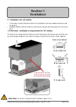
Page 11: ...mmand CentreTM exhausting through the kick space should be used to provide adequate ventilation in all conditions Ancillary components are not shown in these diagrams C Ducted vent 1 1 Ventilation for...

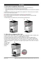
Page 12: ...B1 or side position B2 and without kick space duct fitted to the Command CentreTM For dual exhaust fan cut out dimensions see the instructions provided with the kit B1 B2 A B 1 4 Alternative arrangem...

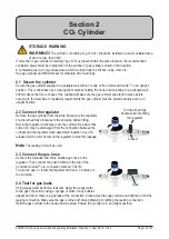
Page 13: ...n upright position 2 2 Connect the regulator Remove the gas cylinder from the strap Make sure the regulator knob is turned fully clockwise to the end stop before fitting Screw the regulator clockwise...

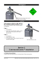
Page 14: ...plied with a sponge or with a brush cover all of the gas joints with a liberal amount of suds Stage 2 1 Turn the gas on 2 Inspect the joints for leaks 3 If any bubbles appear to grow the joint will ne...

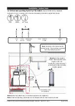
Page 15: ...plastic silicon tubes must be trimmed to size They must have a constant fall to the Command CentreTM Note Mains hose length is 750mm Electrical power cable length is 3 0m nom Position the Command Cent...

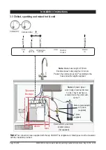
Page 16: ...Note Mains hose length is 750mm Electrical power cable length is 3 0m nom Position the Command CentreTM according to the hose and cable lengths supplied 3 3 Chilled sparkling and mixed hot cold Celsiu...

Page 17: ...uantity of water that will be ejected while the filter flush mode is in operation Open the filter access door on the front of the HydroTap G4 and the filter cartridge will be exposed Located to the re...

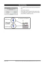
Page 18: ...START STOP button to start and stop the filter flush Open the flush stop cock Allow at least 10 litres of water to flush through the filter Once the filter flush is finished Close the stop cock then p...

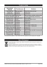
Page 19: ...ntilation Call Zip service Condenser Sensor Open Internal fault Check ventilation Call Zip service Compressor Driver Fault No chilled water Call Zip service A DC Pump is faulty Internal fault Call Zip...

Page 20: ...strict or modify any liability that cannot be excluded restricted or modified or which cannot except to a limited extent be excluded restricted or modified as between the owner or user and Zip under t...

Reviews: