background image

804050UK G4 Commercial chilled and sparkling installation instructions - Sept. 2016 - v3.02 

Page 13 of 20

Section 2

CO

2

 Cylinder

STORAGE  WARNING 
WARNING!


The cylinder ( containing 1kg of CO

2

 ) should be installed in a well ventilated area 

of area no less than 38m

3

.

If more than 1 gas cylinder containing 1kg of CO

2

 is present within the same location, the recommended 

ventilation area should be in proportion to the number of gas cylinders stored in that location.

A ventilated area in a non-enclosed area which could include the kitchen, living room etc.

See gas cylinder and MSDS sheet for complete list of warnings.

2.1


Secure the cylinder

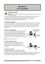
Secure the gas cylinder supplied to a suitable wall, within 1 metre of the Command-Centre

TM

, in an upright 

position. This is undertaken by screwing the metal bar holding the hook-and-loop strap to a cupboard wall, 

200mm above the floor or base of the cupboard. Make sure the gas cylinder can stand in place before 

securing to the wall. Due to regulatory requirements the gas cylinder must be stored securely and in an 

upright position. 

2.2 Connect the regulator

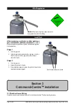
Remove the gas cylinder from the strap. Make sure the regulator 

knob is turned fully clockwise to the end-stop before fitting. 

Screw the regulator (clockwise) onto the cylinder. Be aware that 

some CO

2

 may be discharged from the connection between the 

cylinder and the regulator when assembled together. Any CO

2


released will be cold. Screw on the regulator to stop this leakage.  

Note

 The leaking CO

2

 will be cold.

2.3 Connect the gas hose 

Connect the threaded end of the braided gas hose to the 

regulator. Then connect the push fit fitting to the top of the 

Command-Centre

TM

 via  connection marked ‘CO

2

 IN’. 

To turn the gas on, rotate the regulator knob anti - clockwise to 

the end stop. 

2.4 Test for gas leaks

Using soapy water perform a leak test. Apply the soapy water 

to the gas connections using a sponge or brush. If any bubbles 

appear and grow, there is a gas leak at the connection. Clean away the soapy residue and tighten or refit the 

leaking connection. Make sure the gas is turned off when tightening or refitting the leaking connection. 

Refit the gas cylinder to the hook-and-loop strap. Ensure the cylinder is in an upright position.

Turn the knob fully 

clockwise before fitting 

the regulator

Closed

Open

Summary of Contents for Elite HydroTap G4 range

Page 1: ...s Sept 2016 v3 02 Page 1 of 20 Zip HydroTap G4 Installation instructions Filtered chilled and sparkling drinking water for commercial kitchens and tea rooms Affix model number label here 804050UK VENT...

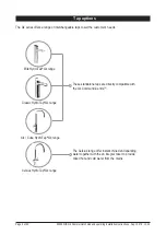
Page 2: ...taps to suit the customer s needs Classic HydroTap G4 range Arc Cube HydroTap G4 range Elite HydroTap G4 range These standalone taps are directly compatible with the G4 Command CentreTM Celsius Hydro...

Page 3: ...he tap head Step 2 Check for adequate ventilation Section 1 Ventilation 1 1 Ventilation on all models 11 12 Step 3 Fit the CO2 gas cylinder Section 2 CO2 cylinder and regulator 2 1 Connect secure and...

Page 4: ...ter cupboard floor has sufficient strength to support the Command CentreTM when full of water see page 9 for weights Before commissioning Check the Command CentreTM has been installed correctly Check...

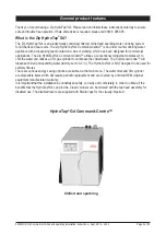
Page 5: ...conventional refrigerant compressor to chill the water and utilises a CO2 gas cylinder to carbonate the chilled water The Command CentreTM will dispense chilled and sparkling water factory set to 3 5...

Page 6: ...s all installation procedures must be carried out by a suitably qualified tradesperson The power cable and power outlet must be in a safe visible position for connection Lifting Take care when lifting...

Page 7: ...nd CentreTM is rated for 230V 50Hz AC operation Do not remove the cover of the appliance under any circumstances without first isolating the appliance from the power supply The Zip HydroTap G4 Command...

Page 8: ...flexible braided hose and positioned so that the connection point and the stop cock will not be obstructed when all the undersink units are installed For Zip HydroTap 160 125 160 175 models a 220 240V...

Page 9: ...x D x H mm with air duct Dry weight kg Chilled and sparkling N A 175 no 1x13A 0 45 N A 336 x 476 x 335 36kg Note Chilled and sparkling water will continue to be dispensed after the rated capacity has...

Page 10: ...in accordance with IEE regulations See Technical specification page 9 for power ratings Note Check all cable and hose lengths against inlet outlet positions before proceeding see sections 2 3 pages 13...

Page 11: ...mmand CentreTM exhausting through the kick space should be used to provide adequate ventilation in all conditions Ancillary components are not shown in these diagrams C Ducted vent 1 1 Ventilation for...

Page 12: ...B1 or side position B2 and without kick space duct fitted to the Command CentreTM For dual exhaust fan cut out dimensions see the instructions provided with the kit B1 B2 A B 1 4 Alternative arrangem...

Page 13: ...n upright position 2 2 Connect the regulator Remove the gas cylinder from the strap Make sure the regulator knob is turned fully clockwise to the end stop before fitting Screw the regulator clockwise...

Page 14: ...plied with a sponge or with a brush cover all of the gas joints with a liberal amount of suds Stage 2 1 Turn the gas on 2 Inspect the joints for leaks 3 If any bubbles appear to grow the joint will ne...

Page 15: ...plastic silicon tubes must be trimmed to size They must have a constant fall to the Command CentreTM Note Mains hose length is 750mm Electrical power cable length is 3 0m nom Position the Command Cent...

Page 16: ...Note Mains hose length is 750mm Electrical power cable length is 3 0m nom Position the Command CentreTM according to the hose and cable lengths supplied 3 3 Chilled sparkling and mixed hot cold Celsiu...

Page 17: ...uantity of water that will be ejected while the filter flush mode is in operation Open the filter access door on the front of the HydroTap G4 and the filter cartridge will be exposed Located to the re...

Page 18: ...START STOP button to start and stop the filter flush Open the flush stop cock Allow at least 10 litres of water to flush through the filter Once the filter flush is finished Close the stop cock then p...

Page 19: ...ntilation Call Zip service Condenser Sensor Open Internal fault Check ventilation Call Zip service Compressor Driver Fault No chilled water Call Zip service A DC Pump is faulty Internal fault Call Zip...

Page 20: ...strict or modify any liability that cannot be excluded restricted or modified or which cannot except to a limited extent be excluded restricted or modified as between the owner or user and Zip under t...

Reviews: