background image

Page 6 of 20 

   804050UK G4 Commercial chilled and sparkling installation instructions - Sept. 2016 - v3.02

Important safety instructions

This manual contains important safety and installation instructions for the Zip HydroTap

®

G4.

Please read all warnings, installation requirements and installation instructions before installing any Zip 

HydroTap

®

G4. This system must be installed in accordance with water supply byelaws, 

current IEE regulations and relevant local authority byelaws.

Safety

This appliance is not intended for use by children under 8 years or persons (including 

children under 8 years) with reduced physical, sensory or mental capabilities, or lack of 

experience and knowledge, unless they have been given supervision or instruction concerning the use of the 

appliance by a person responsible for their safety. Children should be supervised to ensure that they do not 

play with the appliance. Cleaning and user maintenance shall not be made by children without supervision.

Refrigerant 

The Zip HydroTap

®

G4 Command-Centre

TM

 contains R134A refrigerant under pressure. Maintenance of the 

refrigeration unit must be carried out by an accredited service provider or qualified refrigeration technician.

Qualifications 

If the power cable is damaged it must be repaired only by a qualified technician. To avoid hazards, all 

installation procedures must be carried out by a suitably qualified tradesperson. The power cable and power 

outlet must be in a safe visible position for connection.

Lifting

Take care when lifting the Zip HydroTap

®

G4. The Command-Centre

TM

 may exceed safe lifting limits. If 

you feel this is beyond your personal capabilities, please seek assistance with the lift. The weight of the 

Command-Centre

TM

 is marked on the packaging. Do not lift the Command-Centre

TM

 by the front cover or any 

of its connections. Refer to the technical specification, see page 9, for the weight of the product.

Airflow

The Zip HydroTap

®

G4 operates within the ambient temperature range 5ºC - 35ºC. Proper air circulation 

must be provided. The system will operate satisfactorily only if the recommended air gaps are provided. See 

Section 1 'Ventilation', page 11, for correct installation to prevent overheating. The vent kit supplied must be 

fitted.

Frost protection

If the HydroTap

®

G4 is located where the ambient air temperature could fall below 5ºC when the heater is 

not in use, do not turn off the appliance electrically. This safeguard does not offer the same protection to the 

connecting pipework and fittings.

o

Positioning


It is important to ensure the Command-Centre

TM

 is positioned in an accessible area close to the floor level. 

The Command-Centre

TM 

must have it’s base mounted in a horizontal position with all inlets and outlets facing 

up. The tap must be located above the Command-Centre

TM

. See  Section 3, Command-Centre

TM

 installation.

Summary of Contents for Elite HydroTap G4 range

Page 1: ...s Sept 2016 v3 02 Page 1 of 20 Zip HydroTap G4 Installation instructions Filtered chilled and sparkling drinking water for commercial kitchens and tea rooms Affix model number label here 804050UK VENT...

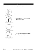
Page 2: ...taps to suit the customer s needs Classic HydroTap G4 range Arc Cube HydroTap G4 range Elite HydroTap G4 range These standalone taps are directly compatible with the G4 Command CentreTM Celsius Hydro...

Page 3: ...he tap head Step 2 Check for adequate ventilation Section 1 Ventilation 1 1 Ventilation on all models 11 12 Step 3 Fit the CO2 gas cylinder Section 2 CO2 cylinder and regulator 2 1 Connect secure and...

Page 4: ...ter cupboard floor has sufficient strength to support the Command CentreTM when full of water see page 9 for weights Before commissioning Check the Command CentreTM has been installed correctly Check...

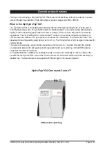
Page 5: ...conventional refrigerant compressor to chill the water and utilises a CO2 gas cylinder to carbonate the chilled water The Command CentreTM will dispense chilled and sparkling water factory set to 3 5...

Page 6: ...s all installation procedures must be carried out by a suitably qualified tradesperson The power cable and power outlet must be in a safe visible position for connection Lifting Take care when lifting...

Page 7: ...nd CentreTM is rated for 230V 50Hz AC operation Do not remove the cover of the appliance under any circumstances without first isolating the appliance from the power supply The Zip HydroTap G4 Command...

Page 8: ...flexible braided hose and positioned so that the connection point and the stop cock will not be obstructed when all the undersink units are installed For Zip HydroTap 160 125 160 175 models a 220 240V...

Page 9: ...x D x H mm with air duct Dry weight kg Chilled and sparkling N A 175 no 1x13A 0 45 N A 336 x 476 x 335 36kg Note Chilled and sparkling water will continue to be dispensed after the rated capacity has...

Page 10: ...in accordance with IEE regulations See Technical specification page 9 for power ratings Note Check all cable and hose lengths against inlet outlet positions before proceeding see sections 2 3 pages 13...

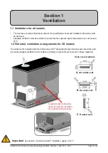
Page 11: ...mmand CentreTM exhausting through the kick space should be used to provide adequate ventilation in all conditions Ancillary components are not shown in these diagrams C Ducted vent 1 1 Ventilation for...

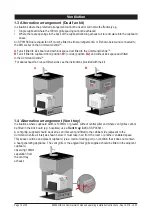
Page 12: ...B1 or side position B2 and without kick space duct fitted to the Command CentreTM For dual exhaust fan cut out dimensions see the instructions provided with the kit B1 B2 A B 1 4 Alternative arrangem...

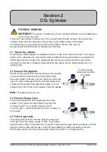
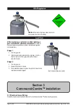
Page 13: ...n upright position 2 2 Connect the regulator Remove the gas cylinder from the strap Make sure the regulator knob is turned fully clockwise to the end stop before fitting Screw the regulator clockwise...

Page 14: ...plied with a sponge or with a brush cover all of the gas joints with a liberal amount of suds Stage 2 1 Turn the gas on 2 Inspect the joints for leaks 3 If any bubbles appear to grow the joint will ne...

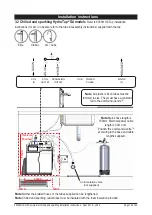
Page 15: ...plastic silicon tubes must be trimmed to size They must have a constant fall to the Command CentreTM Note Mains hose length is 750mm Electrical power cable length is 3 0m nom Position the Command Cent...

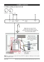
Page 16: ...Note Mains hose length is 750mm Electrical power cable length is 3 0m nom Position the Command CentreTM according to the hose and cable lengths supplied 3 3 Chilled sparkling and mixed hot cold Celsiu...

Page 17: ...uantity of water that will be ejected while the filter flush mode is in operation Open the filter access door on the front of the HydroTap G4 and the filter cartridge will be exposed Located to the re...

Page 18: ...START STOP button to start and stop the filter flush Open the flush stop cock Allow at least 10 litres of water to flush through the filter Once the filter flush is finished Close the stop cock then p...

Page 19: ...ntilation Call Zip service Condenser Sensor Open Internal fault Check ventilation Call Zip service Compressor Driver Fault No chilled water Call Zip service A DC Pump is faulty Internal fault Call Zip...

Page 20: ...strict or modify any liability that cannot be excluded restricted or modified or which cannot except to a limited extent be excluded restricted or modified as between the owner or user and Zip under t...

Reviews: